 13/2/06
I ordered kit 8 this morning.
13/2/06
I ordered kit 8 this morning.
13/2/06
I ordered kit 8 this morning.
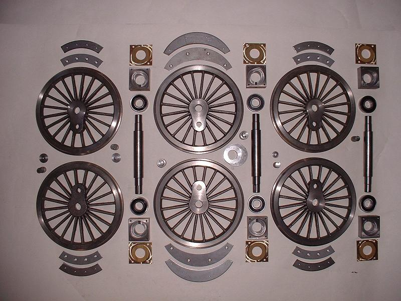
14/2/06 Kit 8 arrived at midday today. It consists of the six driving wheels, their crankpins and balance weights, and their axles, bearings and axleboxes. There is also the eccentric that fits on the main axle and drives the water pump. Two of the driving wheels (on the left in the photograph) don't have their central bosses fully machined, and so I shall probably ask for these to be replaced. The crank pin hole on one other is slightly off centre in its boss, and I'll check whether this will be visible after the coupling rods are fitted before deciding whether to ask for this one to be replaced as well. Apart from this everything looks fine - the wheels seem quite a tight fit on the axles and so should run true.
15/2/06 I'm waiting to sort out the replacement of the wheels, and in the meantime I've completed the detailing of the front of the tender, which I've described under kit 4.
 16/2/06
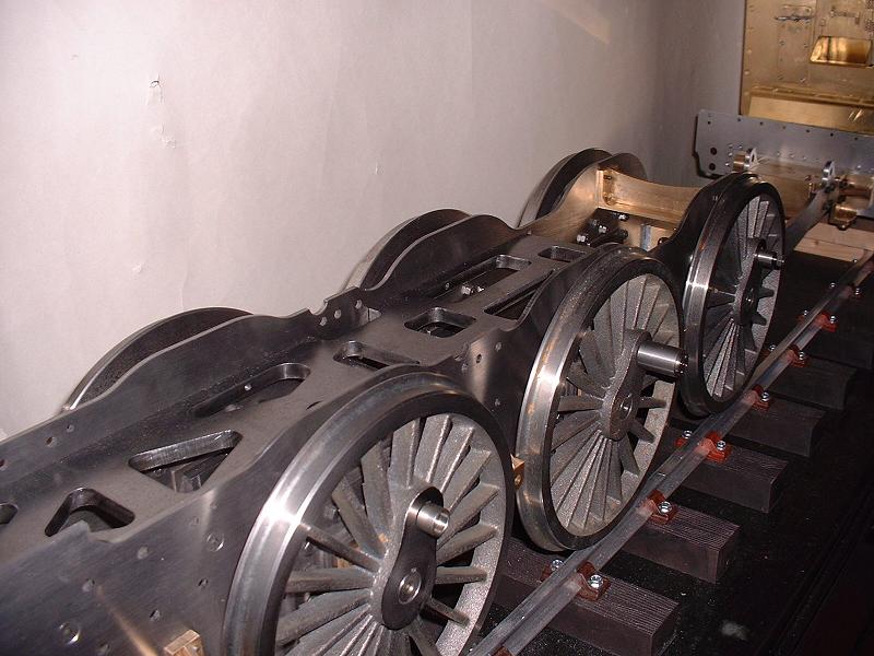
Debbie at Modelworks is happy to replace the three driving wheels, but has no replacements in stock, so I shall have to wait two or three weeks for a new batch to be made. This is no great hardship, since I can carry on with other things in the meantime. I fitted the axleboxes into the horns - four of the six horns were too tight at their lower ends and I eased them with a file. I fitted the bearings, axlebox covers, axles, wheels and crankpins, without glueing anything, and they all spin nicely.
16/2/06
Debbie at Modelworks is happy to replace the three driving wheels, but has no replacements in stock, so I shall have to wait two or three weeks for a new batch to be made. This is no great hardship, since I can carry on with other things in the meantime. I fitted the axleboxes into the horns - four of the six horns were too tight at their lower ends and I eased them with a file. I fitted the bearings, axlebox covers, axles, wheels and crankpins, without glueing anything, and they all spin nicely.
17/2/06 The next job is to fit the balance weights to the three good wheels. These consist of plates bolted together behind and in front of the spokes, with the gap between them filled with a mixture of Araldite and metal filings. On the real locomotive the gap is filled with lead, but I've been alerted by Richard R to the fact that not all the gaps between the spokes are filled in this way. This photograph shows an example. I shall try and find out a bit more about this before fitting the weights.
18/2/06 I've finished fitting the axleboxes and I've glued the bearings into them. I've been contacted by Nigel, a volunteer at the Great Central Railway where 70013 is being restored, and I've asked if he can check the balance weights for me.
19/2/06 I've been contacted by Barry, who has completed all the kits up to date. He and Edward have both alerted me to a problem with the motion gear that Modelworks are currently working to resolve. I'm going to be away on holiday for the next week, so no more updates until 28 February.
 28/2/06
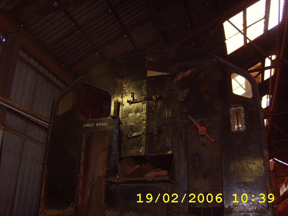
Back to the freezing cold after a lovely sunny week in the Canaries. I've placed the three good wheels on the left hand side and I will file the steel keys to fit the slots in the axles and crankpins. These keys need to be a close fit, but not excessively tight. I will also clean up and fit the balance weight plates, but Nigel has not yet been able to find out about the balance weights on 70013 because its wheels are away having their tyres turned at the moment. However, he's sent me some nice photos of the main frames, bogie and cylinders, and this picture of the tender front confirms that my improvements to the model are pretty much correct. I posted my query about the balance weights on the Model Engineering Clearing House (http://modeleng.proboards20.com) before I went on holiday and this gave rise to a discussion about wheel balancing in general. Britannias seem to have had a bad reputation for hard riding and 'hammering', perhaps because it is more difficult to balance a two-cylinder motion than three or four cylinders. I came to the conclusion that the vibration or hammering effect on a model is relatively less than on the full size locomotive. I explained my reasoning as follows: To keep the numbers simple, assume that we have a 1/10th scale model. We would expect to run it at about 1/10th scale speed, ie 9mph instead of 90mph flat out. So the revs per minute of the wheels would be the same on the model and full size locos. If we look at the simple case of a completely unbalanced crankpin, ignoring coupling rods etc, the centrifugal or hammering force would be proportional to (crankpin mass x rpm squared x distance of crankpin from centre of wheel). For the same rpm this means that the hammering force on the real loco would be 10,000 times greater - the crankpin mass being 10 cubed times greater, and the radius being 10 times greater. The static weight on the track is only 1,000 times greater. So the hammering force as a percentage of axle load increases in direct proportion to the scale of the loco. The model would have to go at (square root 10) times scale speed - ie about 30mph - to get the same hammering effect. I guess this explains why nobody has found the need to balance wheels on models.
28/2/06
Back to the freezing cold after a lovely sunny week in the Canaries. I've placed the three good wheels on the left hand side and I will file the steel keys to fit the slots in the axles and crankpins. These keys need to be a close fit, but not excessively tight. I will also clean up and fit the balance weight plates, but Nigel has not yet been able to find out about the balance weights on 70013 because its wheels are away having their tyres turned at the moment. However, he's sent me some nice photos of the main frames, bogie and cylinders, and this picture of the tender front confirms that my improvements to the model are pretty much correct. I posted my query about the balance weights on the Model Engineering Clearing House (http://modeleng.proboards20.com) before I went on holiday and this gave rise to a discussion about wheel balancing in general. Britannias seem to have had a bad reputation for hard riding and 'hammering', perhaps because it is more difficult to balance a two-cylinder motion than three or four cylinders. I came to the conclusion that the vibration or hammering effect on a model is relatively less than on the full size locomotive. I explained my reasoning as follows: To keep the numbers simple, assume that we have a 1/10th scale model. We would expect to run it at about 1/10th scale speed, ie 9mph instead of 90mph flat out. So the revs per minute of the wheels would be the same on the model and full size locos. If we look at the simple case of a completely unbalanced crankpin, ignoring coupling rods etc, the centrifugal or hammering force would be proportional to (crankpin mass x rpm squared x distance of crankpin from centre of wheel). For the same rpm this means that the hammering force on the real loco would be 10,000 times greater - the crankpin mass being 10 cubed times greater, and the radius being 10 times greater. The static weight on the track is only 1,000 times greater. So the hammering force as a percentage of axle load increases in direct proportion to the scale of the loco. The model would have to go at (square root 10) times scale speed - ie about 30mph - to get the same hammering effect. I guess this explains why nobody has found the need to balance wheels on models.
 1/3/06
I fitted the crankpin and axle keys to the three left-hand wheels - the keys just needed a small amount of filing to get a good fit. I also cleaned up and attached the balance weight plates, and lightly filed the wheel castings to remove high spots. This is about as much as I can do on kit 8 at the moment, pending replacement of the other three wheels. I'll leave the filling of the balance weights for the time being to see if I can get any further information about 70013, and I don't intend to glue the axles and crankpins until I get the coupling rods in kit 12. I'll order kit 9 tomorrow.
1/3/06
I fitted the crankpin and axle keys to the three left-hand wheels - the keys just needed a small amount of filing to get a good fit. I also cleaned up and attached the balance weight plates, and lightly filed the wheel castings to remove high spots. This is about as much as I can do on kit 8 at the moment, pending replacement of the other three wheels. I'll leave the filling of the balance weights for the time being to see if I can get any further information about 70013, and I don't intend to glue the axles and crankpins until I get the coupling rods in kit 12. I'll order kit 9 tomorrow.
2/3/06 I've decided that I need to make a start on the painting, so I bought a compressor from Argos (�69.99, including a rather fearsome-looking nail gun which I'll probably never use) and I ordered a hose from Shesto with a water trap and the right connectors for the compressor and my Badger 200-3 airbrush. I chose to start on the bogie, since it is relatively small and well hidden, and I brush-painted the etch primer onto the brass parts. I also spent a large part of the day moving my website to a new Geocities plan that removes the advertising and the hourly bandwidth limits for $4.95 a month, and I acquired (with lots of advice from BurrellBuilder) the 'www.britanniabuilder.co.uk' URL from 123-reg, a division of Pipex, for the princely sum of �6.09 for two years.
3/3/06 No sign of kit 9 yet. The etch primer on the brass parts of the bogie seems reassuringly scratch-resistant. I brush-painted some of the steel parts with rust-stabilising primer.
 4/3/06
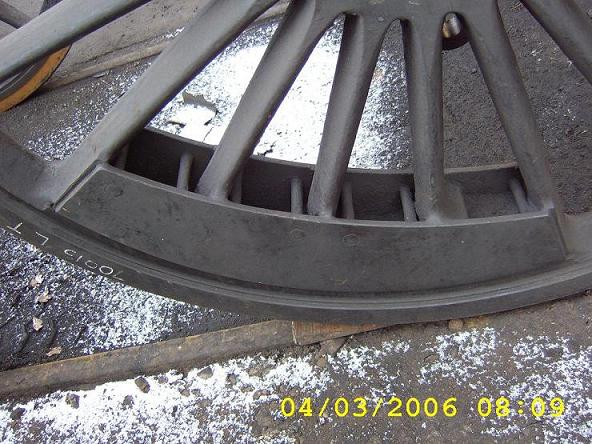
I filled some countersunk screw heads after the first coat of rust-stabilising primer, and applied a second coat. This primer scratches much more easily than the etch primer, but perhaps it will harden with time. Nigel sent me 12 photos of 70013's driving wheels, which have returned from their tyre turning. This is a sample of the left trailing wheel. The position seems to be that each of the leading and trailing wheels has its rearmost gap (as viewed when the balance weight is at the bottom) half-filled, and the adjacent gap somewhat less than half-filled, and each driving wheel has the second and third gaps from the front completely filled. I suspect that the asymmetry on the leading and trailing wheels may be to compensate for the fact that the plates are not directly opposite the crankpins, but half a spoke forward, and the asymmetry on the driving wheels may be to balance the return crank that hangs backwards from the end of the crankpin. I've been told that after the builders had balanced the first few Britannia wheels individually they adopted an average for all the other locos, since the roller-bearing axles wouldn't fit in the balancing machine and it was so tedious to put the wheels onto plain axles to balance them. This photo also shows that the leading and trailing balance plates are not quite the right shape on the model - they should be wider at the centre than the ends. However, I don't intend to start filing them.
4/3/06
I filled some countersunk screw heads after the first coat of rust-stabilising primer, and applied a second coat. This primer scratches much more easily than the etch primer, but perhaps it will harden with time. Nigel sent me 12 photos of 70013's driving wheels, which have returned from their tyre turning. This is a sample of the left trailing wheel. The position seems to be that each of the leading and trailing wheels has its rearmost gap (as viewed when the balance weight is at the bottom) half-filled, and the adjacent gap somewhat less than half-filled, and each driving wheel has the second and third gaps from the front completely filled. I suspect that the asymmetry on the leading and trailing wheels may be to compensate for the fact that the plates are not directly opposite the crankpins, but half a spoke forward, and the asymmetry on the driving wheels may be to balance the return crank that hangs backwards from the end of the crankpin. I've been told that after the builders had balanced the first few Britannia wheels individually they adopted an average for all the other locos, since the roller-bearing axles wouldn't fit in the balancing machine and it was so tedious to put the wheels onto plain axles to balance them. This photo also shows that the leading and trailing balance plates are not quite the right shape on the model - they should be wider at the centre than the ends. However, I don't intend to start filing them.
5/3/06 I changed my mind and filed the leading and trailing balance plates to give an inside radius equal to those on the driving wheels, and they do look better. I also brush-painted black enamel onto part of the bogie - the result does not look quite as smooth as I'd hoped, despite using the correct sable brushes, and so I may switch to spray painting.
29/5/06 Having now fitted the coupling rods and connecting rods, I've decided that two of the three wheels with cosmetic defects can be used. The one with a small unmachined area on the crankpin boss can be used as the driving wheel, since this boss is completely covered by the large boss on the coupling rod. The one with the crankpin boss cast 1mm offcentre can be used as the leading wheel, where the problem is not visible behind the coupling rod boss and the rest of the motion. This just leaves the wheel with the central boss completely unmachined to be replaced. It's disappointing that Modelworks have still not produced a new batch of wheels after three months - I know of at least one other builder waiting for replacements. Anyway, I've now started filing the balance weights for the two wheels.
30/5/06 I fitted the balance plates to the driving wheel. I've decided to half-fill the spaces between the plates, using just the slow-setting Araldite supplied without the metal filings mixed in. I think this will be more realistic since the real locomotive has only 2 pockets out of the total of 30 fully filled, and the lead filling has a smooth surface. The Araldite can be carefully dripped into each pocket and it evens itself out nicely. It's going to be a slow process, since each pocket needs to be vertical and the Araldite takes 6 hours to set. I used plasticine to plug the slight gap between the outer plate and wheel rim while the glue was setting.
18/7/06 I've now received the three replacement driving wheels from Debbie. I've decided to use two new wheels on the right-hand leading and trailing axles, and keep the original wheel on the driving axle - although this has a slight defect on the crankpin boss, it's completely covered by the large central coupling rod boss, and I've already fitted its balance plates. The crankpin holes on the new wheels seem to be a few thou smaller than on the original batch, and I had to use emery cloth to get them to fit. Once I've finished fitting the keys I'll be able to do an initial check for free rotation of the wheels and coupling rods. I'll return the third wheel to Debbie tomorrow along with the two defective ones, and also drop off my smokebox to have the rivet holes redrilled.
20/7/06 I've now fitted the keys to the right-hand wheels, and the chassis rolls very freely with just the coupling rods fitted - there's just a very slight tight spot at front dead centre on the right-hand side, which seems to be caused by the leading axle on that side being very slightly too far back. I might try slackening off the hornblock and see if I can move it forward a fraction. I haven't glued the axles and crankpins yet, but they are a good fit without any backlash so hopefully they will still roll freely when they are glued. I returned the wheels and smokebox to Debbie yesterday, and I saw the boilers being constructed - the boilermaker has a lot on his plate at the moment, with boilers for the 7 1/4" A3s and A4s and the Bagnall as well as the Britannia.
21/7/06 On closer inspection the tight spot at front dead centre was caused by the right rear coupling rod, and I relieved it by easing the knuckle pin very slightly. I started fitting the balance plates to the two new wheels. When I visited the factory on Wednesday I collected kit 16, which consists of some globe valves, part of the reversing gearbox and other odds and ends. Since nothing can be done with it until we get the boilers, I will leave it to one side and not write it up yet. It does also contain the replacement return cranks and eccentric rods and their bearings, so builders who have not already requested these may prefer to wait for this kit.
30/7/06 I've been dismantling the axle assemblies in order to glue the wheels and crankpins. I've been advised to use Loctite 7063 degreaser instead of the usual cellulose thinners to clean these critical joints prior to glueing, so I ordered an aerosol can of this from RS Components. I also ordered some Loctite 222 screwlock and 243 nutlock - I intend to lock all the nuts and bolts when I eventually reassemble after painting.
1/8/06 I painted the brass cover plates of the axleboxes, since they won't be accessible once the wheels are glued in place. I glued the crankpins to the wheels, using the Loctite 7063 which arrived this morning to clean the surfaces. In one case the glue grabbed before I could fully insert the crankpin, but I was able to knock it out again before it set completely. It's useful to have a small hammer and drift to hand in case this happens, since every second counts. I did read somewhere that in hot weather the parts can be cooled in a fridge or freezer to prolong the time before the Loctite sets, although I haven't tried this.
3/8/06 Yesterday I glued the axlebox bearings to the axles, and this morning I glued the three left-hand driving wheels to the axles. We're off to the boat this evening, so no more updates for the next few days.
 11/8/06
Just back from a week's sailing - we cruised to Cherbourg and Guernsey, and came back across the Channel yesterday in winds touching 30 knots, which made for a rather bumpy ride. The picture shows our boat in a crowded St Peter Port, Guernsey, in the foreground next to the pontoon. I now need to glue the right-hand wheels to the axles and reassemble the valve gear in preparation for testing on compressed air at Modelworks next Wednesday.
11/8/06
Just back from a week's sailing - we cruised to Cherbourg and Guernsey, and came back across the Channel yesterday in winds touching 30 knots, which made for a rather bumpy ride. The picture shows our boat in a crowded St Peter Port, Guernsey, in the foreground next to the pontoon. I now need to glue the right-hand wheels to the axles and reassemble the valve gear in preparation for testing on compressed air at Modelworks next Wednesday.
12/8/06 I reassembled the wheels and coupling rods to check that they still rotated freely prior to glueing the right-hand wheels, which they did. I then glued the right-hand leading and driving wheels to their axles. When these have set tomorrow I'll check for free running again before finally glueing the trailing wheel to its axle. Ian at Modelworks recommended the following procedure to avoid quartering problems when I met him at the Harrogate show:
13/8/06 The motion still rotates freely with five wheels glued, so I glued the final wheel to the trailing axle. I refitted the motion brackets, the axle pump and the two front axles and springs.
14/8/06 I refitted the trailing axle and springs. The wheels and coupling rods turn reasonably freely, although there's now a slight stiffness at two of the 45 degree positions which suggests a slight quartering problem - rather surprising, given the care I took to check everything as I went along, and the fact that there was no perceptible free play in the key of the final wheel before I glued it. However, I can turn the motion quite easily with finger and thumb on the main crankpin, so I'm sure it will free up after a little running in.
21/12/06 I've resumed filling the balance weights as described on 30/5/06 above. This involves putting masking tape on the spokes and the outer balance plate, positioning one set of pockets on one side at the 6 o'clock position and dripping slow-setting Araldite into them, to a level a couple of mm below the top of the plates. They then need 6 hours to harden before moving on to the next set, but the Araldite levels out well and the result does look realistic.
| Next Kit | Previous Kit | Index |