 5/12/05
I ordered kit 4 this afternoon.
5/12/05
I ordered kit 4 this afternoon.
5/12/05
I ordered kit 4 this afternoon.
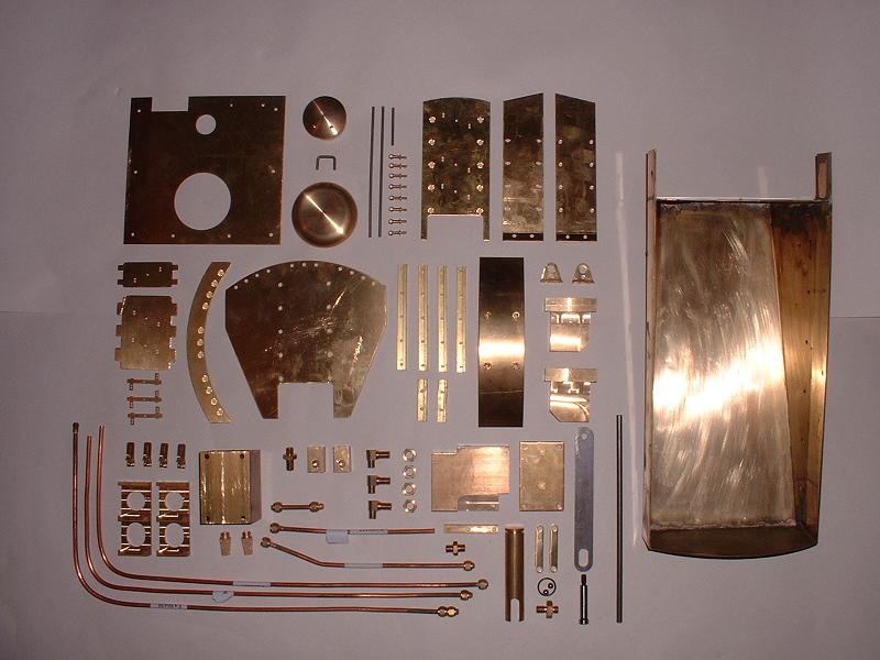
8/12/05 Kit 4 arrived this afternoon - the courier is normally very prompt, but had a Christmas backlog this week. I checked and photographed the contents, which include all the remaining parts for the tender. There is some pretty heavy brassware - the large water pickup cover alone weighs over 1lb. The main components are:
 9/12/05
I started to assemble the tender handpump, which is nicely machined from solid brass. I spent a little while polishing the parts up. The three 2BA bolts securing the linkage are a rather loose fit in their 5mm holes - 2BA is 4.7mm - resulting in a slightly sloppy movement of the pump mechanism, so I shall try to find some M5 brass or stainless bolts to replace them. The pump works nicely, shooting a jet of water a foot in the air.
I bolted the three pipe connectors through the tender base - these connect to copper pipes running forward under the tender floor as follows:
9/12/05
I started to assemble the tender handpump, which is nicely machined from solid brass. I spent a little while polishing the parts up. The three 2BA bolts securing the linkage are a rather loose fit in their 5mm holes - 2BA is 4.7mm - resulting in a slightly sloppy movement of the pump mechanism, so I shall try to find some M5 brass or stainless bolts to replace them. The pump works nicely, shooting a jet of water a foot in the air.
I bolted the three pipe connectors through the tender base - these connect to copper pipes running forward under the tender floor as follows:
 10/12/05
No progress today - we went down to our boat in Lymington and had an invigorating sail across to Yarmouth on the Isle of Wight for lunch and a walk along the Solent shore. Here's a photo of the sun setting over the Needles channel on the way back, just to make a change from brasswork (although the tones are rather similar). Back to the brasswork tomorrow!
10/12/05
No progress today - we went down to our boat in Lymington and had an invigorating sail across to Yarmouth on the Isle of Wight for lunch and a walk along the Solent shore. Here's a photo of the sun setting over the Needles channel on the way back, just to make a change from brasswork (although the tones are rather similar). Back to the brasswork tomorrow!
11/12/05 Woken up bright and early by the enormous explosion at the Buncefield oil terminal which is only about four miles away from us. Luckily the wind wasn't blowing our way. I did a trial assembly of the front locker - it fits together nicely, although the curved roof piece needs to be bent a little more to fit the profile of the roof, and will benefit from a couple of additional brackets at its rear corners to prevent it flexing. The brackets that hold it to the locker walls also needed to be spaced in with a nut between them and the walls to line up with the holes in the roof. I also tried fitting the coal bunker, which comes already soldered together and looks as though it will fit well with only a small amount of filing.
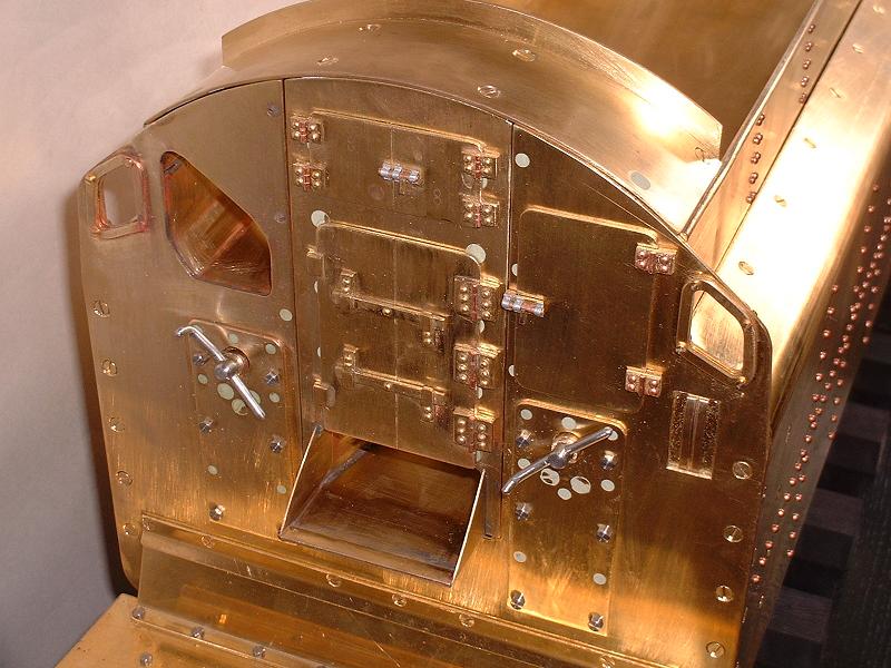
12/12/05 I dismantled the front locker again and filed and polished the parts, and bolted it together again properly. The large and small locker doors show only a rudimentary amount of detail and I intend to improve them by making better simulations of the hinges and of the locking plates for the rotating bars. This photograph shows the large locker doors on 70000. One oddity is that the hinges on the right hand door look much meatier than those on the left!
13/12/05 Richard P has solved the riddle of the locker door hinges - the doors must operate concertina-fashion with a hinge down the central joint, so the plates on the left are not hinges but locating lugs. I shall simulate the doors accordingly. I made the extra brackets to support the outer ends of the curved locker roof - I'm ashamed to say that I countersank one of the holes too deeply and the screw pulled through, so I've had to turn the roof round and drill new holes, leaving the old ones to be filled in later. I started on the large locker doors, engraving a deep line down the centre and modifying the left hand side to have two small lugs rather than three hinges. The rotating bars and locking plates need to be offset to the left - the pivot is on the left-hand door - so there are more holes to be filled in.
14/12/05 I continued with the detailing of the locker doors, which will probably take a couple of days. The set of four tender steps arrived from Doug Hewson - they are exquisitely detailed, although possibly slightly vulnerable to being knocked and bent. I also checked into the correct sizing of the four lamp irons on the rear of the tender - the ones provided look rather wide at 8mm, and indeed the correct width as quoted by the Miniature Railway Supply Co for their lamps is 4.5mm - just as well I checked before rivetting them on. I've ordered two of their lamps to make doubly sure of the fitting.
15/12/05 I started to drill the locker door hinge plates for their rivets, but snapped my 1.6mm drill which prevented further progress today.
 16/12/05
The replacement for the faulty copper pipe arrived from Modelworks this morning - very prompt service. I went to Chronos to replenish my stock of drills, and bought a few other goodies - I find it impossible to visit an Aladdin's cave like that without buying more than I intended - and I continued on the locker door detailing. I've also decided to cannibalise a couple of inches from the 6mm steel handpump handle to make a better spindle for the handbrake handle - I haven't been able to find a supplier of small quantities of metric steel rod.
16/12/05
The replacement for the faulty copper pipe arrived from Modelworks this morning - very prompt service. I went to Chronos to replenish my stock of drills, and bought a few other goodies - I find it impossible to visit an Aladdin's cave like that without buying more than I intended - and I continued on the locker door detailing. I've also decided to cannibalise a couple of inches from the 6mm steel handpump handle to make a better spindle for the handbrake handle - I haven't been able to find a supplier of small quantities of metric steel rod.
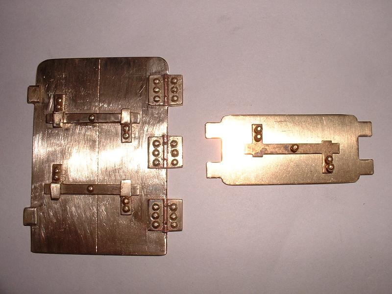
17/12/05 I completed the main locker door detailing - see the photo alongside, with the unadorned small locker door for comparison. I'll probably tackle the small door tomorrow, although I haven't yet found a clear photo of its latching arrangement. I don't think it has the large locking bar as supplied, judging by this photograph. The slides on either side of the cutout in the front bulkhead look rather unsightly after all the other improvements to the tender front, and I've realised that I can probably dispense with them by adding angles to the sides of the removable section to prevent it moving forwards. It can't move backwards because it presses against the internal bulkhead behind it. This would also avoid the slides scraping the paint off the front of the removable section. I shall experiment with this arrangement tomorrow.
 18/12/05
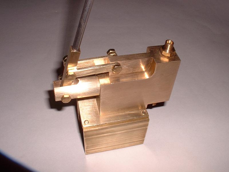
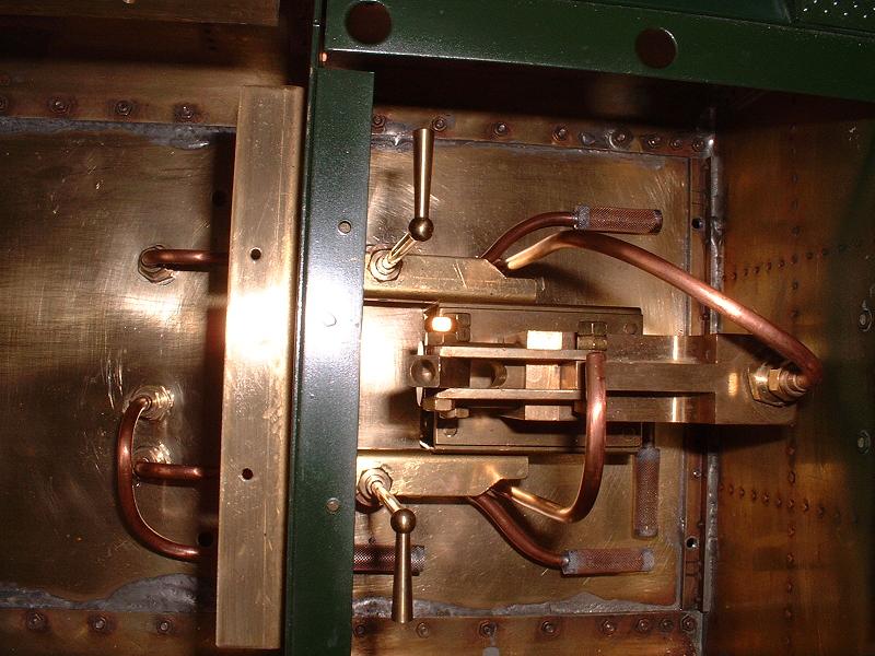
I made the modification described above, using two 9cm lengths of brass 1/4"x1/16" angle fixed with countersunk screws into the existing holes in the front of the side plates of the locker assembly. It works perfectly and gives a flat surface to the front bulkhead - a great improvement. I started fitting hinge plates to the small locker door, and I installed the replacement copper pipe between the handpump outlet and the floor fitting - bending these pipes to the correct radius needs some care. This photograph shows the handpump, the pipework and the two inlet filters for the handpump and the injector feed. The open-ended pipe towards the top of the picture is the return from the axlepump bypass. The removable pump handle is at the top of the picture.
18/12/05
I made the modification described above, using two 9cm lengths of brass 1/4"x1/16" angle fixed with countersunk screws into the existing holes in the front of the side plates of the locker assembly. It works perfectly and gives a flat surface to the front bulkhead - a great improvement. I started fitting hinge plates to the small locker door, and I installed the replacement copper pipe between the handpump outlet and the floor fitting - bending these pipes to the correct radius needs some care. This photograph shows the handpump, the pipework and the two inlet filters for the handpump and the injector feed. The open-ended pipe towards the top of the picture is the return from the axlepump bypass. The removable pump handle is at the top of the picture.
19/12/05 I continued detailing the small locker door, adding rivets to the hinges and fabricating a bolt to replace the locking bar.
20/12/05 I finally completed the small locker door, as well as doing all my Christmas shopping - earlier than usual this year.
 21/12/05
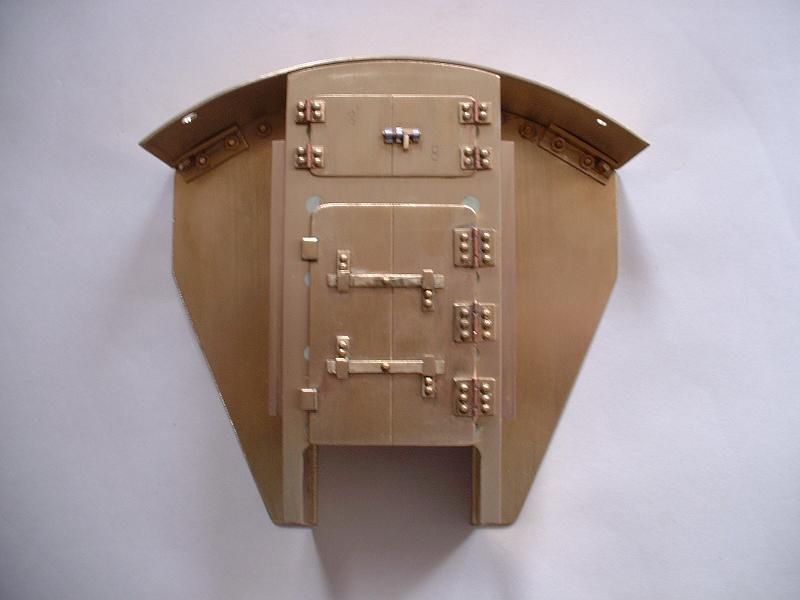
I filled the countersunk screws on the locker front that are partially covered by the locker doors, using a Loctite 'chip and dent' two-part filler from Halfords. Richard R has used something similar from B&Q which he says gave good results. I smoothed this down with wet-and-dry sandpaper and then fixed the two locker doors. This photograph shows the results, which I'm quite pleased with - I think the extra effort was worthwhile. Even my wife concedes that the bolt on the upper door is quite dinky. If the real Oliver Cromwell doesn't have a bolt like this, I shall suggest to the National Railway Museum that they get one forthwith. Update 26/3/06 - I've now seen the tender undergoing restoration at Loughborough and its bolt is spot on! The hinges are perhaps slightly too large - equivalent to 5.5" at full scale - but I couldn't make them much smaller and still get the rivets in. Note also the extra fixings at the outside ends of the locker roof, and the angles on the sides of the locker front that replace the slides on the surrounding bulkhead. The superfluous holes at the front corners of the roof still need to be filled.
21/12/05
I filled the countersunk screws on the locker front that are partially covered by the locker doors, using a Loctite 'chip and dent' two-part filler from Halfords. Richard R has used something similar from B&Q which he says gave good results. I smoothed this down with wet-and-dry sandpaper and then fixed the two locker doors. This photograph shows the results, which I'm quite pleased with - I think the extra effort was worthwhile. Even my wife concedes that the bolt on the upper door is quite dinky. If the real Oliver Cromwell doesn't have a bolt like this, I shall suggest to the National Railway Museum that they get one forthwith. Update 26/3/06 - I've now seen the tender undergoing restoration at Loughborough and its bolt is spot on! The hinges are perhaps slightly too large - equivalent to 5.5" at full scale - but I couldn't make them much smaller and still get the rivets in. Note also the extra fixings at the outside ends of the locker roof, and the angles on the sides of the locker front that replace the slides on the surrounding bulkhead. The superfluous holes at the front corners of the roof still need to be filled.
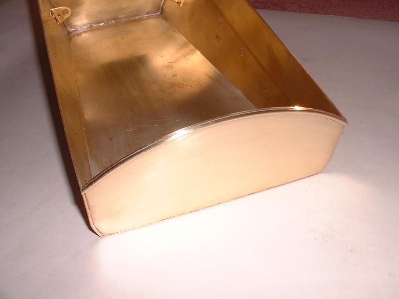
22/12/05 I cleaned up the coal bunker, using wet and dry sandpaper to remove all the flux residue and discolouration caused by the silver soldering of the end plates - this took about an hour, but the result looks very good. There is just a small depression in the brass on each of the side walls in line with the front soldered joint, doubtless caused by the heat of the soldering torch, but a dab of filler will cover this. The coal bunker fitted beautifully into the tender, with hardly any filing - I just needed to take a little off the sides of the removable locker section to allow it to slot in between the sides of the bunker. The curved roof piece sits perfectly on the bunker sides and the front bulkhead. It might be worth fitting a bracket between the front bulkhead and the front of each bunker side to prevent the latter flexing. I removed the bunker again and fitted the forward lifting lugs within the bunker, and the water filter boxes under each side of the tender body. I also removed the superfluous top rung from the ladder on the rear bulkhead (see kit 3, 8/12/05).
 23/12/05
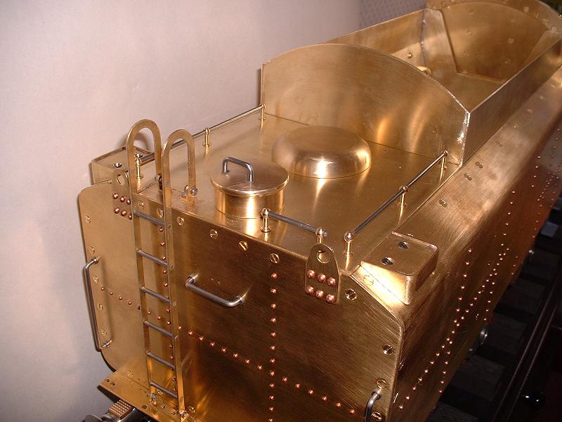
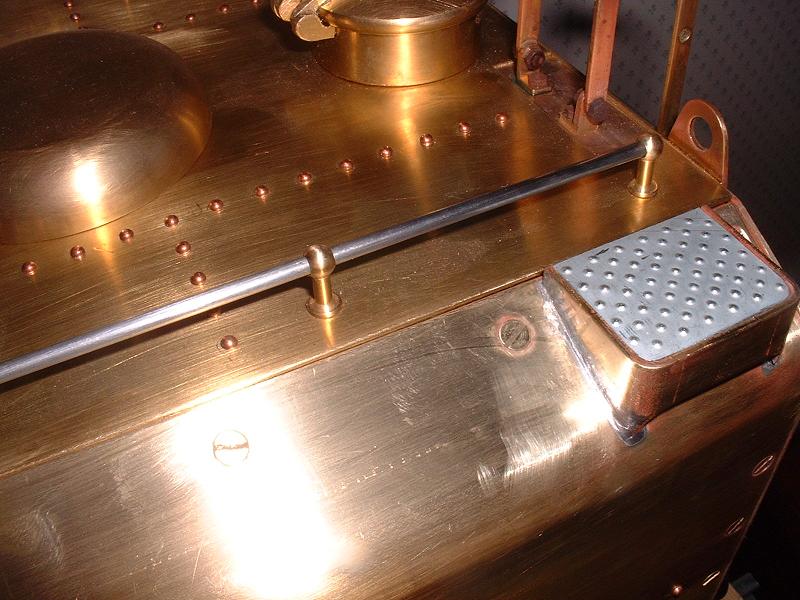
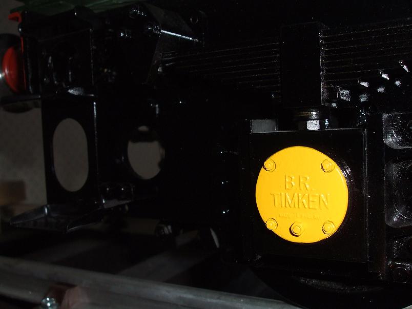
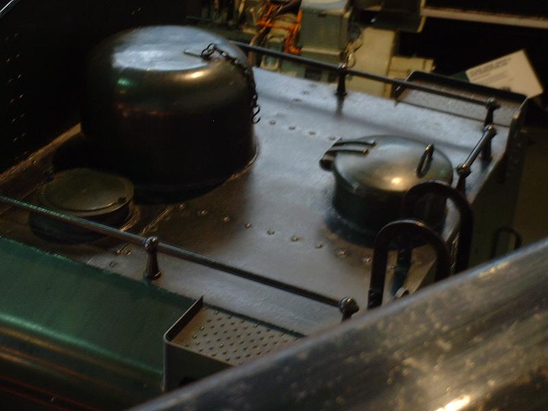
I assembled the roof of the rear section of the tender behind the coal bunker - simply a matter of filing and polishing the brass plate and fitting the three handrails and their stanchions. It fits perfectly into the space between the surrounding platework. The two heavy brass domes fit into holes in the plate. In the real tender the larger front dome covers the riser pipe for the water pickup unit that scoops water up from a trough between the rails, and the smaller rear dome is for filling from a water tower. Although on many Britannias the front dome was much higher than the one supplied, it looks as though the low dome is correct for Oliver Cromwell, judging by a rather long-distance photograph in my book of Britannias. Modelworks recommend glueing the rear dome in place and leaving the front one loose to give access to the handpump and to fill the tender with water, but I've tapped the underside of the rear dome and fixed it with two M3x6 bolts, and I'll probably do the same for the front dome and rely on lifting off the entire roof section for access - it will be easier to lift the handrails than to try to get a grip on the dome.
23/12/05
I assembled the roof of the rear section of the tender behind the coal bunker - simply a matter of filing and polishing the brass plate and fitting the three handrails and their stanchions. It fits perfectly into the space between the surrounding platework. The two heavy brass domes fit into holes in the plate. In the real tender the larger front dome covers the riser pipe for the water pickup unit that scoops water up from a trough between the rails, and the smaller rear dome is for filling from a water tower. Although on many Britannias the front dome was much higher than the one supplied, it looks as though the low dome is correct for Oliver Cromwell, judging by a rather long-distance photograph in my book of Britannias. Modelworks recommend glueing the rear dome in place and leaving the front one loose to give access to the handpump and to fill the tender with water, but I've tapped the underside of the rear dome and fixed it with two M3x6 bolts, and I'll probably do the same for the front dome and rely on lifting off the entire roof section for access - it will be easier to lift the handrails than to try to get a grip on the dome.
24/12/05 I started to fit the front and rear tender steps that I bought from Doug Hewson. I fixed the front steps, which fit nicely with only a small adjustment to the top fixing holes - the tender frames need to be carefully marked and drilled for the two stays that support the bottom of the steps, fixed with tiny 10BA bolts. Although the steps are fabricated from fairly thin steel, the stays do hold them quite rigidly. However, the brackets for the rear steps didn't seem quite right, and will need to be either modified or replaced to get the steps in the correct position.
26/12/05 The tender is almost fully assembled now, but there are still quite a number of things that need to be done to complete it. I've listed them below, and I'll update this page from time to time as I complete them. I fitted the drawbar, which should have the slot at the tender end, contrary to what the instructions say. I made a new spindle for the handbrake handle (see kit 3, 3/12/05) from a 35mm length of 6mm steel rod - this engages properly in the rear hole in the gearbox and gives a much smoother movement. The 6mm exposed end, cross-drilled for the 3mm handle and framed by an M6 washer glued to the plate, is also much closer to scale than the large boss on the spindle supplied. I removed the front handrails (see kit 3, 5/12/05) - I'm now almost certain that Oliver Cromwell doesn't have them.
27/12/05 I put screws in the superfluous holes for the rear steps in the tender base - the Doug Hewson steps are attached to the frames and buffer beam rather than to the bottom of the tank. I adjusted the height of the coal bunker slightly, by filing the bolt holes - it needed to be lowered by 2mm at the front. I fixed a support bracket to the left-hand rear tender side to improve the rigidity of the joint (see kit 3, 7/12/05).
28/12/05 I made a new spindle for the water pickup unit handle to match the new handbrake spindle (see 26/12/05 above) and fixed it into a brass plate screwed to the back of the bulkhead, angled slightly upwards to match the handbrake spindle. I started to modify the fixing brackets for Doug Hewson's rear tender steps, which I think I can do satisfactorily without troubling Doug.
29/12/05 I filled in the superfluous holes in the front bulkhead and locker roof. I've confirmed with Richard R the correct positioning of the rear steps - he has measured up the BR standard tender of Evening Star. I've decided that the steps will be better secured if I replace or supplement the angle bracket between the steps and the buffer beam with an angle bracket between the top of the steps and the frames. I'll need to wait until next week to get hold of the sheet metal to make these brackets, so there won't be much progress to report now until next week. Richard also tells me that he received kit 12, the motion gear, before Christmas, and confirmed that the kit does have the correct fish-bellied rather than fluted coupling rods for Oliver Cromwell in its later years.
31/12/05 I experimented with the springs, now that the tender is up to full weight. It weighs 28 kilos (62lb), which makes me doubtful about the advertised weight of 170lb for the complete locomotive plus tender, probably derived from the old Winson version of the kit. I think that Modelworks' use of cast iron and brass in place of the brass and aluminium of the Winson version, although a great improvement, may have pushed up the weight significantly. Despite this there is no noticeable deflection of the springs from the flat position - they are very stiff. I'm using the longest steel leaf, all 9 bronze leaves, and the shortest steel leaf. I have not attempted to put any pre-bend into the springs, because I'm not confident that I could do this evenly across all the leaves of all the springs. It would probably look a bit more attractive if there was uniform pre-bend in the springs, but as long as they don't take on a noticeable reverse bend then I'll be content. If I wanted to ride on the tender rather than on a driving truck behind the tender, it might be necessary to put some bend into the springs and perhaps use more of the steel leaves. I hasten to add that I've slimmed down from 14st7 to 12st6 since I retired, having exchanged business lunches for plenty of fresh air and exercise! I tried turning the spring shackles the other way up on one side of the tender (see kit 2, 16/11/05), using washers to space out the bolt head from the underside of the springs by about 3mm. This gives a better ride height, with the axleboxes just about 1mm above the mid-point of the horn cheeks - it raises the tender by about 2mm. I will adopt this arrangement, filing the rounded ends of the bolts flush with the top surface of the shackles.
2/1/06 I replaced the M6 washers behind the handbrake and water pickup unit handles (see 26/12/05 above) with 9mm brass collars around the shafts. Richard R suggested this - it is closer to the real shape. Tomorrow I shall have to brave the rush hour on the M25 - I retired a year ago, but my Chairman has asked me to return for a week or two to give him some advice. It's flattering to be asked, but it risks interfering with the serious business of model engineering! I will order kit 5, the locomotive frames, within the next day or two.
 6/1/06
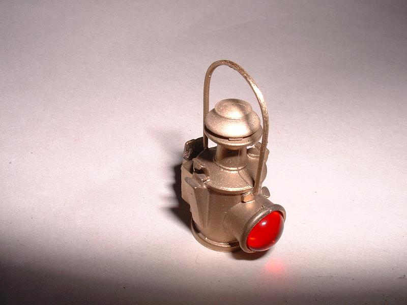
Well I survived 3 days commuting on the M25 and I'll probably just need to do another few days over the next few weeks. Kit 5 arrived yesterday and the lamps arrived today (see 14/12/05 above) - they are beautifully detailed - so I've got plenty to be getting on with now. I filed the upright of one of the lamp irons down to 4.5mm wide and 14mm high and bolted it to the rear of the tender with 10BA bolts - Britannia's tender seems to have bolts rather than rivets here. I've been contacted by Harry, who is also building Oliver Cromwell, and he has sent me a long list of his improvements to the tender - I've added some more items to the list below as a result. If there are any other Britannia Builders out there, do please contact me at the email address shown on the index page - it's nice to get feedback and compare notes. The email address only appears if you have Javascript enabled in your browser, to reduce the risk of spam.
6/1/06
Well I survived 3 days commuting on the M25 and I'll probably just need to do another few days over the next few weeks. Kit 5 arrived yesterday and the lamps arrived today (see 14/12/05 above) - they are beautifully detailed - so I've got plenty to be getting on with now. I filed the upright of one of the lamp irons down to 4.5mm wide and 14mm high and bolted it to the rear of the tender with 10BA bolts - Britannia's tender seems to have bolts rather than rivets here. I've been contacted by Harry, who is also building Oliver Cromwell, and he has sent me a long list of his improvements to the tender - I've added some more items to the list below as a result. If there are any other Britannia Builders out there, do please contact me at the email address shown on the index page - it's nice to get feedback and compare notes. The email address only appears if you have Javascript enabled in your browser, to reduce the risk of spam.
14/1/06 I've now adjusted and fitted the remaining three lamp irons to the rear of the tender, and I've replaced the 2BA bolts by M5 brass bolts on the handpump linkage (see 9/12/05 above), which has cured the slight sloppiness in the action. I bought a 13" length of 6mm silver steel from Chronos to replace the handpump handle that I cannibalised earlier to make the new handbrake and water pick-up spindles. I've also replaced the 4mm pin in the handbrake linkage by a lock-nutted M4 bolt, since the pin was too short to take the split pin supplied. I've removed the rather unsightly M6 washers that I fitted to the brake pullrod connecting pins to stop them flopping from side to side (see kit 2, 18/11/05) and I've ground the shoulders back on the pins instead, allowing the pullrod ends to be clamped tightly between their connecting plates. I've rounded the corners on the buffer steps and shaped the draw hook to a point, as suggested by Harry.
 15/1/06
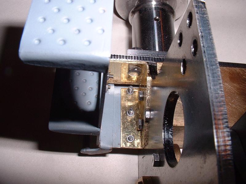
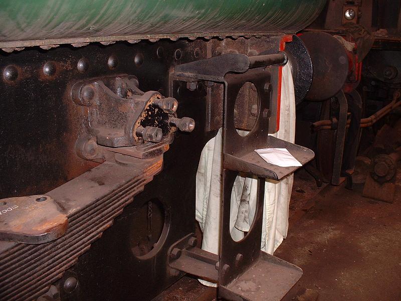
I inverted the rest of the spring shackles (see 31/12/05 above), spacing the bolt heads from the underside of the springs with 3 M5 brass washers, and filing the rounded ends of the bolts flush with the top of the shackles. I'll probably make the brass spacer plates suggested by Harry at some stage - these are 1/4" by 1" by 1 3/8", with detailing on the outer edge, and the bolt head would rest in an indentation in the centre of the top face. I also made a top mounting bracket for Doug Hewson's rear steps (see 24/12/05 above) - a piece of 22swg brass bolted to the third and fourth bolts down on the frame, bent round behind the buffer beam and attached to the outer lower buffer mounting bolt, bent over the top to bolt with 10BA bolts to the three holes in the top of the steps, and bent round from the buffer beam to bolt with small-headed 10BA bolts to the two holes in the upper rear of the steps. The front face of the vertical step plate is 1.6mm out from the frames, which I believe is correct. A complicated piece of work, and extremely fiddly to fit, but very rigid. The bottom bracket should be trivial by comparison. This very close-up photo reveals that I didn't draw-file the underside edges of the tender frame and buffer beam - I must have been in too much of a rush to build the first kit. I'll have to rectify this when I partly dismantle the tender to paint it.
15/1/06
I inverted the rest of the spring shackles (see 31/12/05 above), spacing the bolt heads from the underside of the springs with 3 M5 brass washers, and filing the rounded ends of the bolts flush with the top of the shackles. I'll probably make the brass spacer plates suggested by Harry at some stage - these are 1/4" by 1" by 1 3/8", with detailing on the outer edge, and the bolt head would rest in an indentation in the centre of the top face. I also made a top mounting bracket for Doug Hewson's rear steps (see 24/12/05 above) - a piece of 22swg brass bolted to the third and fourth bolts down on the frame, bent round behind the buffer beam and attached to the outer lower buffer mounting bolt, bent over the top to bolt with 10BA bolts to the three holes in the top of the steps, and bent round from the buffer beam to bolt with small-headed 10BA bolts to the two holes in the upper rear of the steps. The front face of the vertical step plate is 1.6mm out from the frames, which I believe is correct. A complicated piece of work, and extremely fiddly to fit, but very rigid. The bottom bracket should be trivial by comparison. This very close-up photo reveals that I didn't draw-file the underside edges of the tender frame and buffer beam - I must have been in too much of a rush to build the first kit. I'll have to rectify this when I partly dismantle the tender to paint it.
18/1/06 I've now made and fitted all four brackets for the rear steps - it was very time-consuming work. I've ordered kit 6 today, so I shall proceed with that before doing further work on the tender.
21/1/06 I've now decided not to add the tool tunnel, vents and stays to the inside of the coal bunker, since this is a working area when the model is being steamed, but instead to make up a wooden platform with dummy coal glued on top to place in the coal bunker when the model is on display. I'll still make the tool tunnel opening in the front of the tender. I bought some half-round 1/8" brass beading for the top of the coal bunker from Blackgates Engineering at the Alexandra Palace show yesterday, along with the paint as mentioned under kit 6. I've decided to add the rivets to the logo area on the tender sides, having been assured by Phoenix that transfers can be placed successfully on top of rivets by making small nicks in the transfers.
27/1/06 I rivetted the remaining holes in the logo area on the tender sides, and fitted a dust cover to the handbrake gearbox - I made this from a U-shaped piece of 22swg brass fitted over the top and sides and secured with an M3 bolt tapped into the top of the gearbox. The gearbox sounds quite smooth now, after packing it with grease.
 28/1/06
I started soldering the 1/8" half-round brass beading to the rim of the coal bunker. I hadn't been looking forward to this, since I've never attempted soldering large areas of brasswork before. In the event, after a few false starts and some difficulty in getting the gas torch hot enough to melt the solder as the sheet brass conducted the heat away, I succeeded in soldering the curved strip across the rear of the bunker. Perhaps it was beginner's luck, but the beading follows the curve of the edge absolutely perfectly. I just hope that it doesn't come adrift again when I solder the beading along the sides.
28/1/06
I started soldering the 1/8" half-round brass beading to the rim of the coal bunker. I hadn't been looking forward to this, since I've never attempted soldering large areas of brasswork before. In the event, after a few false starts and some difficulty in getting the gas torch hot enough to melt the solder as the sheet brass conducted the heat away, I succeeded in soldering the curved strip across the rear of the bunker. Perhaps it was beginner's luck, but the beading follows the curve of the edge absolutely perfectly. I just hope that it doesn't come adrift again when I solder the beading along the sides.
29/1/06 I have now soldered the beading along both sides of the coal bunker. I bought a new Taymar 3000 gas torch from Homebase, which is much hotter than my old one, and I made a tool to position the beading by cutting the profile (ie a right angle with a half-round indentation) into the end of a strip of brass and then drew this tool along behind the flame to position the beading exactly on the edge of the brass and hold it down as the solder set. This arrangement gave a perfect alignment which I'm very pleased with. It took far longer to chisel away the excess solder than to make the joint itself. My next job is to add the extra rivets to the coal bunker and the top plate.
30/1/06 I started adding the rivets to the top plate - one row across and two rows fore-and-aft at 9mm spacings, each in line with the corresponding columns of rivets on the tender sides and rear. Progress here is now temporarily halted after snapping my third and final 1.6mm drill. It needs some care to get the holes exactly in a straight line - a lateral error of half a millimetre is quite obvious. I use a centre punch, then a small centre drill, then the 1.6mm drill, and inspect the position carefully after the hole is started so that I can move it slightly if necessary by angling the drill and then bringing it upright again. In one case where the hole was drilled out of line I managed to elongate it with a small engraving tool in the Dremel and then hammer the rivet in while pressing it to the correct side with the rivet snap. There must be a market for rivets with off-centre heads! I've also marked out the coal bunker for the rivets on the sides and rear. The left-hand side has two double columns of five rivets, in line with the first two columns on the tender sides (strictly speaking the rear column of the front pair and the front column of the rear pair are in line with their respective columns on the tender sides); I've spaced these rivets 7mm vertically and 4mm between the columns. These rivets are not present on the right-hand side - presumably this gets its rigidity from the tool tunnel welded inside it. Then on both sides there is a group of five rivets that hold the vents. The rearmost of these is in line with the third column of rivets on the tender side, with 8mm horizontally between the rivets, the outer two being 7mm down from the beading and the inner three 3mm down. On the rear face there are two double columns of seven rivets, in line with the columns on the rear of the tender; I've spaced these 8mm apart vertically, with the lowest pair almost flush with the top plate, and 4mm between the columns. All these measurements are derived from a combination of drawings and photographs - I think they're about right. If anyone disagrees, speak now before I drill the holes!
 31/1/06
I finished adding the rivets to the top plate, and I painted some rubberised roofing paint onto a spare piece of brass to see how well it sticks, prior to waterproofing the tank joints. My wife and I are going to visit the National Railway Museum in York tomorrow, where I'll be able to check the details on Evening Star's tender, which is the same type as Oliver Cromwell's. It should be a nice day out, and less than two hours up the main line from Stevenage.
31/1/06
I finished adding the rivets to the top plate, and I painted some rubberised roofing paint onto a spare piece of brass to see how well it sticks, prior to waterproofing the tank joints. My wife and I are going to visit the National Railway Museum in York tomorrow, where I'll be able to check the details on Evening Star's tender, which is the same type as Oliver Cromwell's. It should be a nice day out, and less than two hours up the main line from Stevenage.
1/2/06 Well we had an excellent day out at the NRM, and the entry for 30/1/06 above now shows the corrected rivet positions. I also measured up the fittings on the tender front. This photograph shows the coal bunker rivets on Evening Star - they are rather faint in the photo, but all visible if you look closely.
2/2/06 Today I fixed all 58 rivets in the sides and rear of the coal bunker. I also ordered kit 7, the front bogie, and I asked Doug Hewson to supply some dimpled plate for the top rear steps.
7/2/06 I made dummy hinges for the water filler, as suggested by Harry.
10/2/06 I started on the extra details for the front of the tender, making the coal chute from 22swg brass. I widened the sides of the coal chute opening slightly to 60mm, flush with the side walls of the removable section. The coal chute projects 27mm and the sides are 27mm high, with notches at the top to locate them under the front face. The base of the projecting part is horizontal, with a rounded strip of 1/4x1/16" brass soldered across the front, and the base slopes down inside the opening and is soldered to the underside of the side walls.
11/2/06 I started making the additional locker door above the water pickup handle. This is 60mm high by 39mm wide, with the inside edge flush with the edge of the cutout and the lower edge 5mm above the top of the water pickup plate. Richard R has pointed out that the bolt halfway up the inner edge of this door should be just below the upper hinge on the large central doors, as shown here, but on the model it clashes with the hinge - this is because the central doors are not as tall as they should be (77mm instead of 84mm) and their hinges are slightly too large and too far from the top and bottom edges. Update 6/4/06: when I saw 70013 at the GCR I noticed that the top right corner of this door is cut to a larger radius, and the top hinge is lower down. This appeared to be a later modification because the piece cut out had been welded back into the frame - probably the opening so close to the edge of the tender had weakened the frame.
12/2/06 I completed the hinges and bolt for the locker door, and I decided to move it 3mm in from the edge of the cutout so that the bolt does not have to span the cutout. This also leaves space for the bolt to be placed halfway up the door and alongside the top hinge of the central doors. I cut the slot for the water gauge - 26mm high by 14mm wide, 15mm in from the tender side (it should really be 18mm in, but I moved it 3mm along with the locker door) and with the bottom edge 12mm below the top of the water pickup plate.
13/2/06 I completed the water gauge by fitting a backing plate and a curved gauge plate filed from 1/4" wide brass with a 1mm slot filed down the centre line. I started marking out the cutout for the tool recess above the handbrake plate. I've placed the bottom edge 14mm above the top of the handbrake plate, with the inner side 8mm from the edge of the central cutout - it should be more like 5mm, but I needed to allow space for the wall of the tool recess to clear the angle of the removable central section. I've placed the outer side 35mm from the outer edge of the tender - it should be 32mm, but I needed to allow more space for the thickness of the coal bunker side. Thus the width of the cutout is 36mm instead of the 42mm taken from my measurements of Evening Star's tender. The maximum height of the cutout is 46mm, the height of the inner vertical side is 26mm, and the angle in the lower outer corner is 11mm high by 7mm wide.
 15/2/06
I cut the outline of the tool recess and made up a brass shell to fit behind this, extending back almost to the front of the bunker and leaving just enough space for the removable central section to slot down behind it. This shell was quite tricky to lay out since I wanted to get the authentic narrowing of the inner face - I cut a template in thin aluminium from a drinks can using scissors, and then cut, bent and soldered the shell. This photograph shows the completed improvements to the tender front - central door locks and hinges, additional locker door with bolt and hinges, water gauge, coal chute, tool recess, countersunk screws, corrected bolt positions on handle plates, improved handle spindles, no handrails, and no external guides for the removable section.
15/2/06
I cut the outline of the tool recess and made up a brass shell to fit behind this, extending back almost to the front of the bunker and leaving just enough space for the removable central section to slot down behind it. This shell was quite tricky to lay out since I wanted to get the authentic narrowing of the inner face - I cut a template in thin aluminium from a drinks can using scissors, and then cut, bent and soldered the shell. This photograph shows the completed improvements to the tender front - central door locks and hinges, additional locker door with bolt and hinges, water gauge, coal chute, tool recess, countersunk screws, corrected bolt positions on handle plates, improved handle spindles, no handrails, and no external guides for the removable section.
6/3/06 Using my measurements from Evening Star's tender, I reduced the depth of the rear flange from 18mm to 10mm, redrilled 8 of the 12 holes to get them all in a straight line, cut a recess 28mm wide by 5mm deep in the centre of the flange above the draw hook, and secured the flange with small-headed (4.5mm AF) 6BA nuts and bolts.
20/4/06 I removed the brass steps from the tops of the buffer stocks and replaced them with the castings that I bought from Doug Hewson (see kit 10, 1/4/06). I also modified the bottom brackets of the rear steps so that their flanges are on the top, bolted to the two top holes for the guard irons, as shown here.
6/7/06 I decided to try soldering the tank seams rather than using the silicone filler supplied, and started with the front compartment. I used Powerflow flux and lead-free solder from the DIY store which I happened to have lying around, although others have recommended Baker's fluid flux. For each joint I supported the tender at a slight angle so that the solder would flow into the joint, applied the flux with a rounded stick, placed lengths of solder at intervals along the joint, and applied the blowtorch. This gave a continuous bead of solder along the joint, and testing for water-tightness was a formality. I then removed the handpump and pipework from the rear compartment and finished the soldering. The edges of the rear bulkhead were slightly more complicated because of the need to solder around both sides of the angle strips. I temporarily plugged the various holes with nuts and bolts and filled the tender with water. There were no leaks from the soldered joints, and just slight seepage from some of the countersunk screws in the middle bulkhead and from one or two of the rivets. I'm very pleased with the result, although there's a lot of cleaning needed now to remove the flux residue and discolouration.
 10/7/06
I started fitting the dimpled plates that I bought some time ago from Doug Hewson for the top rear tender steps. The plates need filing down to fit inside the flange on the step - see this picture of Evening Star's tender at the National Railway Museum.
10/7/06
I started fitting the dimpled plates that I bought some time ago from Doug Hewson for the top rear tender steps. The plates need filing down to fit inside the flange on the step - see this picture of Evening Star's tender at the National Railway Museum.
17/7/06 I soldered the top steps to the tender, since the angled screws did not seem to hold them particularly securely. This also gives the impression of a welded joint. I then glued the dimpled plates in with Araldite.
18/9/06 Having painted the tender chassis, I now need to prepare the tender body for painting. I started by removing the water filter boxes (easier said than done, since the solder had got to the bolts) so that I can either add extra detail to them or use Doug Hewson's castings. Richard R and Harry L have both bought Doug's castings, but haven't yet fitted them. I also adjusted the alignment of the coal bunker, which involved filing a deeper angle on one of the side supporting bars.
19/9/06 I started checking that all the countersunk screws are below the surface prior to filling, deepening the countersinks where necessary, and fixing the screws with threadlock. I'll need to paint the inside of the front compartment before permanently fitting the front panel, since this will be visible when driving without the removable section. Ian tells me that he has fitted Doug Hewson's filter boxes - it sounds as though quite a bit of work is involved, but I've gone ahead and ordered a set anyway.
21/9/06 I've now finished countersinking and thread-locking all the screws on the tender body. Yesterday I called Modelworks to check on progress with the boilers since my visit a month ago, and was told that the first batch of 10 would be shipped in October, and the next batch of 16 in November. Not brilliant news, but I guess we just have to be patient.
22/9/06 I started polishing the tender to remove the flux residue inside and out, and I tested again for water leaks. The threadlock had eliminated leakage around the screws, but a few rivets had slight seepage so I hammered these down tighter. Debbie emailed me today to say that the castings omitted from kit 14 - chimney, regulator cover, regulator bush and dart handles - have now been received from the suppliers and will be sent out when they have been machined.
25/9/06 I've now finished cleaning the tender and filing the corner joints, and I've etch-primed the countersunk screws and corner joints in preparation for filling them.
27/9/06 Back from a couple of days sailing, enjoying the unseasonably warm weather. I've started filling the countersunk screws on the tender sides. Mark has sent me some photos of his tender after painting, and it looks very good - he said that he had to rig up a tent of plastic sheeting and wear a paper boiler suit to keep the dust at bay. He is planning to experiment with lining pens and pinstripe masking for the tender lining rather than using transfers, so it will be interesting to hear how he gets on. I'd been planning to buy transfers for the lining, although I'm not sure how to go about varnishing them neatly.
 29/9/06
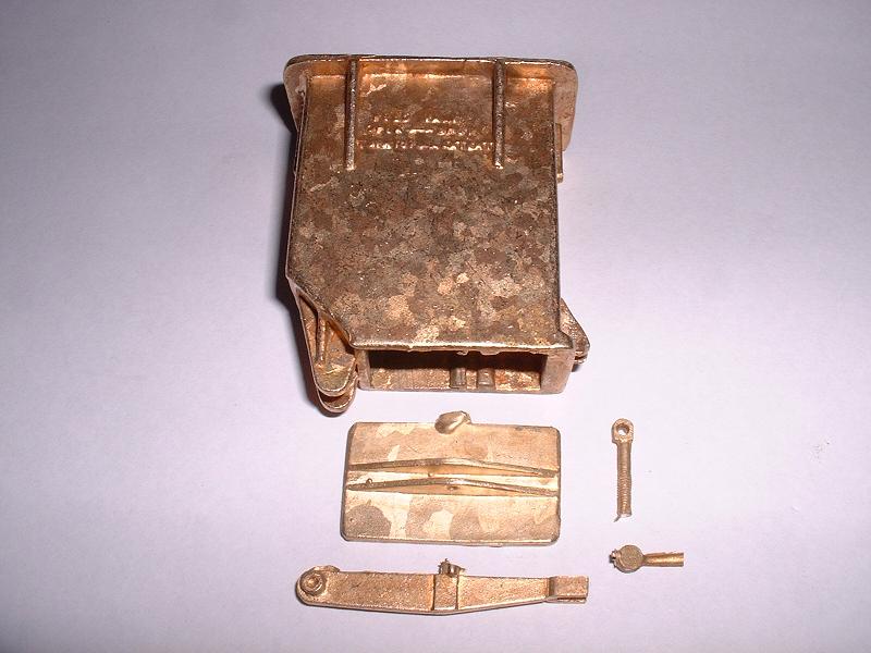
The water filter box castings arrived from Doug Hewson this morning. They are nicely detailed, as shown in this photograph, and can be made up as working filters complete with stop valve and gauze filters, although these parts are not included. I don't intend to do this - I'll retain the water delivery pipes under the tender body as supplied by Modelworks.
29/9/06
The water filter box castings arrived from Doug Hewson this morning. They are nicely detailed, as shown in this photograph, and can be made up as working filters complete with stop valve and gauze filters, although these parts are not included. I don't intend to do this - I'll retain the water delivery pipes under the tender body as supplied by Modelworks.
1/10/06 I started assembling the left-hand filter box - I cut off the top section of the Modelworks filter box to use as the body mounting, and rounded off its outer corners to match the casting. I then attached the casting with 2 M3 socket-head screws inserted up through holes drilled in the top of the casting and tapped into the brass mount. By using socket-head screws I could just reach them with an allen key. I adopted this method of fixing rather than a number of 10BA bolts through the flange of the casting because I wasn't confident of my ability to drill and tap matching holes accurately, although I may still drill and tap the flange and fit cosmetic studs and nuts.
3/10/06 I've ordered a 10BA tap and nuts and bolts from Chronos, along with some 3/16" copper tubing for the dummy water feed pipes leading forward from the water filters. To make the dummy water valve I took an M3x8 brass bolt and filed the head to a 4mm square, and removed the thread near the head by spinning it in an electric drill and filing it down to a shaft diameter of 2.4mm, to match the Imperial measurements shown on Doug's drawings. I then fitted the valve into an M3 hole tapped into the casting.
6/10/06 The bits arrived from Chronos today and I started drilling and tapping 10BA threads into the top flange and the water valve flange. The castings have dimples to locate these holes, but some of the dimples on the top flange are too far in and don't leave room to fit nuts under the flange. I didn't spot this initially and had to cut into the body of the casting with an engraving tool in the Dremel to give space for the nuts. I'm planning to go to Loughborough tomorrow to work on Oliver Cromwell.
8/10/06 I've now fitted all the dummy studs and nuts to both filters, and made the second water valve. I noticed yesterday that Oliver Cromwell has a square head on the left hand valve and a hexagonal one on the right, but I don't intend to take realism that far - square heads seem to be the norm. I also started to fit the hinged flap at the bottom, using 1/16" brass rod to pin the hinges. I might buy an 8BA tap and die to cut a working screw thread for the latch.
 10/10/06
I've now completed the water filters, apart from cutting threads for the latches - I've ordered an 8BA tap and die from Chronos to do this, along with a pipe bending tool for the water pipes. I'll now continue filling the screw holes in the tender body in preparation for painting.
10/10/06
I've now completed the water filters, apart from cutting threads for the latches - I've ordered an 8BA tap and die from Chronos to do this, along with a pipe bending tool for the water pipes. I'll now continue filling the screw holes in the tender body in preparation for painting.
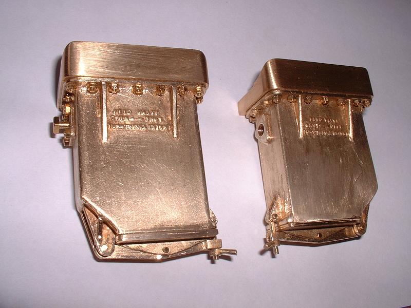
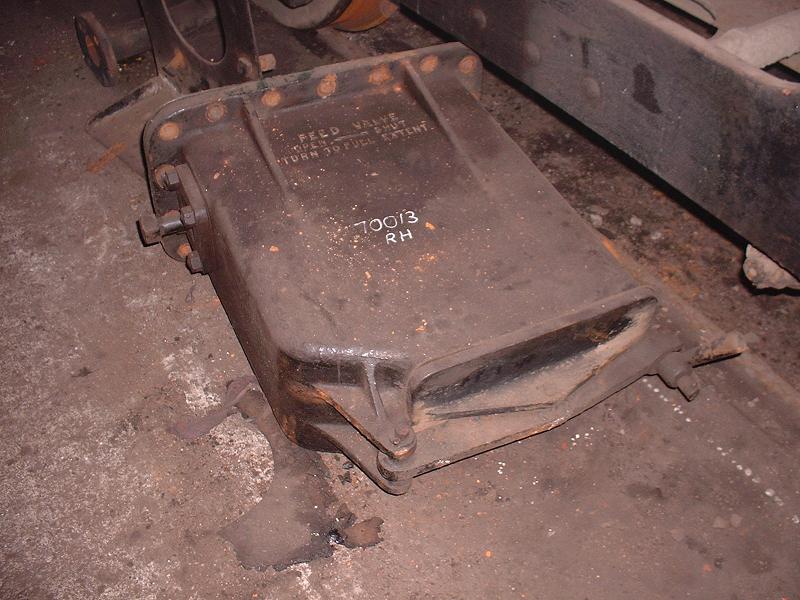
14/10/06 Back from a couple of days sailing, to Ocean Village in Southampton - superb weather for this time of the year. The tools arrived from Chronos and I've cut the threads on the water filter latches. The left-hand picture shows the real filter box from Oliver Cromwell for comparison.
16/10/06 I've now filled all the joints and the countersunk holes on the tender body, except on the front corners because I need to paint the inside of the front compartment before I can permanently attach the front plate.
18/10/06 Yesterday I airbrushed 2-part etch primer onto the inside of the front compartment, the rear surface of the front plate and the underside of the tender, and I've just finished airbrushing the black gloss. I called Brad at Modelworks today to check progress on the boilers and he said that he'd seen the first batch of about 10 on the factory floor and they looked to him to be nearing completion - he thought it would probably take another couple of weeks to finish and test them.
21/10/06 I've attached the front plate to the tender and now need to fill the remaining countersunk screw heads before I can start painting the rest of the tender. I'm determined to get the filler completely flush before I start painting, to avoid the problems that I had with the tender buffer beam (see kit 2, 30/8/06). This may take a few days, with several cycles of filling, rubbing down, and spot painting to check in reflected light. I spoke to Debbie yesterday and she confirmed that I'll be getting one of the first batch of boilers as soon as they are tested and certified, and she also said that the smokeboxes that have been sent back for redrilling (see kit 14) will be done in the next 7-10 days.
24/10/06 I've continued working on the countersunk screw heads. Ian emailed me to say "a friend of mine who is a panel beater by trade advised me that when filling the countersunk screws, if you sand the filler so that it is only in the countersink none on the surrounding metal you will end up with a hollow, even if you use a block. He recommended sanding until you can see the countersink through the filler and feather the edges in with some medium/fine wet & dry." So I've applied a thin layer of Holt's Knifing Putty on top of the existing filler, and started rubbing this down with 1200 grade wet & dry paper - hopefully this will give a flat finish.
26/10/06 A slight setback today - having carefully sanded down the Holt's Knifing Putty to a nice flat finish, I started to clean down the brasswork with cellulose thinners in preparation for etch priming, and found that the thinners dissolved away the putty! I'll have to repeat the exercise using the Loctite chip-and-dent filler that I used originally. The putty was slightly more convenient because it didn't have to be mixed. It will probably still be OK for filling any blemishes that are visible after painting - cellulose thinners cannot be used at this stage anyway because they also dissolve the enamel paint, as I discovered when I first started painting the bogie. I went ahead and etch-primed the bunker, top plate, ladder, water filters and the removable front section, since these parts didn't have any significant amount of putty. I've decided to paint the bunker separately from the tender body and bolt it in only after the tender body has been bolted to the chassis. This means that I can't put filler into the joints along the sides of the bunker, but these joints are a pretty close fit and it saves having to devise some way of capturing the bolts that fix the body to the chassis, which are not accessible once the bunker is in place. It will also allow the bunker to be removed for access if any leaks develop.
28/10/06 Yesterday I airbrushed black enamel onto the removable front section, the inside of the bunker, the water filters and the ladder. The countersinks on the front section show up as very slight hollows in a bright light. I've been contacted by Mark and Rod (a new contact, who's up to kit 14) with advice about filling. Mark recommends fine grade Milliput - a 2-part epoxy which is harder than car body filler and can be smoothed with water - applied and rubbed down in 2 or 3 sessions, allowing 24 hours to harden. Rod uses car body filler, rubs down and then cleans and primes overall, then applies knifing putty to any hollows, sands and primes, repeating until flat. He uses Carat paper from MIRKA rather than wet and dry. The common theme in all this seems to be that excellent results can only be achieved with care and patience! Today I applied dabs of primer to the countersink hollows with a brush, and will rub this down and repeat - if this does not fill the hollows I'll use knifing putty.
31/10/06 I've continued filling and rubbing down - two coats of primer in the hollows were sufficient to bring them up level, so a final spraying session should complete the removable front section. When checking for flatness of the unpainted tender sides by holding them up to the light, I noticed that one of the tender sides had been pulled in by the middle bulkhead, resulting in a slight hollow over quite a large area. I was able to correct this simply by slackening and then re-tightening the M3 bolts holding the angle strips to the bulkhead panel, allowing the body panel to spring flat again. I guess I shouldn't have bolted the angles tightly to the bulkheads before bolting the sides on. We're away for a week's holiday from tomorrow, and Debbie says that the boiler and redrilled smokebox should be ready for me to collect when we get back.
18/11/06 I masked off and cleaned down the main body of the tender with four applications of cellulose thinners, and airbrushed it with 2-part etch primer. I'm using the 2-part etch primer for everything now, since my tin of 1-part has turned to jelly (to be fair to Precision Paints, they do say that it should be used within nine months), and anyway mixing the 2-part is no more effort than diluting the 1-part.
 19/11/06
I broke open my pot of green paint (Precision Paints' P101 post-1954 BR Loco Green) for the first time, and airbrushed one fairly thick coat onto the top plate, the rear and one side of the tender. I used several spotlights to get much better illumination of the job, and this certainly helps to get a uniform finish. By diluting the paint with only about 15-20% thinners and opening the flow fairly wide, I'm getting good coverage in a single coat without any sags. There's a slight 'orange peel' effect, which suggests that I need a touch more thinners to get the paint to flow evenly.
19/11/06
I broke open my pot of green paint (Precision Paints' P101 post-1954 BR Loco Green) for the first time, and airbrushed one fairly thick coat onto the top plate, the rear and one side of the tender. I used several spotlights to get much better illumination of the job, and this certainly helps to get a uniform finish. By diluting the paint with only about 15-20% thinners and opening the flow fairly wide, I'm getting good coverage in a single coat without any sags. There's a slight 'orange peel' effect, which suggests that I need a touch more thinners to get the paint to flow evenly.
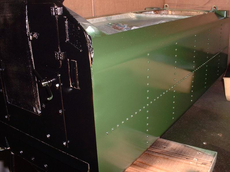
20/11/06 I put the first coat of black on the tender front, along with another coat on the removable front section and other parts. This photo shows the tender body after the first coats of green and black. I didn't bother masking the corner at this stage. The handles and water gauge will be painted red with a brush later. The flashlight gives a very misleading impression of the shade of green - it's actually quite dark, more like the far end in the picture. I've had trouble getting a consistent proportion of thinners when mixing the paint by eye in the small glass airbrush jar, so I've now taken to marking the jar and filling by eye with 20-25ml paint, and then measuring out the required amount of thinners with a 5ml medicine spoon.
22/11/06 Yesterday I lightly rubbed down the green paint with 1200 grade wet&dry, and applied another coat. Most of the countersunk screws are now completely invisible, and the rest can be fixed with a dab of paint or knifing putty. The sides of the coal bunker below the beading have a few scratches where I didn't rub down the excess solder carefully enough, and I may need to strip the paint off these and start again.
 26/11/06
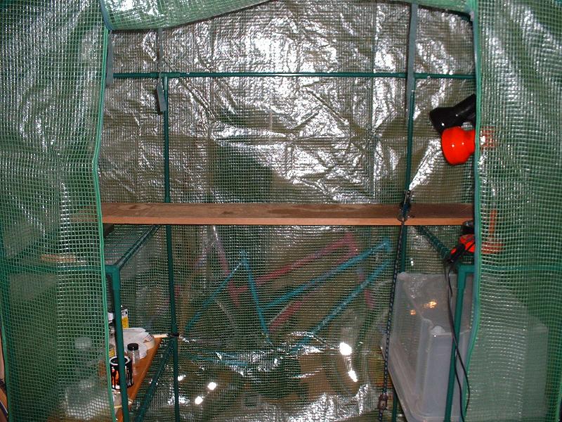
I've spent the past few days carefully rubbing down the tender and filling blemishes with knifing putty. It's all too easy to rub edges down to the bare brass, and I've had to touch these in with etch primer again and wait 24 hours, so it's a slow process. I decided that I need a better painting booth to avoid getting dust on the final coats, so today I bought a small plastic greenhouse (�39.99 from Argos) complete with side shelves and a zip-down front door. I've also bought a new disposable overall which I'll reserve for painting - my other one is covered in muck from working on 70013 at Loughborough. I'll spray the interior of the greenhouse with water to settle the dust before each session, and hopefully this will achieve the desired results. The greenhouse is a bit on the small side - I believe that Homebase do a larger one for about �50 - but I wanted to be able to get my car into the garage when I'm not actually painting. I'm sure that it would be easy to construct a similar booth from timber battens and polythene sheeting.
26/11/06
I've spent the past few days carefully rubbing down the tender and filling blemishes with knifing putty. It's all too easy to rub edges down to the bare brass, and I've had to touch these in with etch primer again and wait 24 hours, so it's a slow process. I decided that I need a better painting booth to avoid getting dust on the final coats, so today I bought a small plastic greenhouse (�39.99 from Argos) complete with side shelves and a zip-down front door. I've also bought a new disposable overall which I'll reserve for painting - my other one is covered in muck from working on 70013 at Loughborough. I'll spray the interior of the greenhouse with water to settle the dust before each session, and hopefully this will achieve the desired results. The greenhouse is a bit on the small side - I believe that Homebase do a larger one for about �50 - but I wanted to be able to get my car into the garage when I'm not actually painting. I'm sure that it would be easy to construct a similar booth from timber battens and polythene sheeting.
29/11/06 I've put a further two coats of green on the tender and it's starting to look pretty good, but I think it will still benefit from another coat or two. The painting booth is a big improvement on the cardboard box that I was using before.
3/12/06 I've rubbed the tender down again and put another coat of green on. The finish is still not quite as good as I would like - the successive passes of the airbrush are not flowing together as uniformly as they should. I suspect that the cold temperature in my garage may be to blame. Also the removable top plate behind the bunker, which was the part mainly affected by 'orange peel' during the first painting session, is proving difficult to rectify - it's difficult to rub down the areas around the rivets satisfactorily. I think I may strip this piece back to bare metal and start again. Perhaps I'm being too fussy - in normal light viewed from a couple of feet away it all looks fine.
4/12/06 I've removed the paint from the top plate by scrubbing with cellulose thinners. It took a reassuringly long time to do this - the paint was very firmly stuck to the brass. I then applied a fresh coat of etch primer. I'll spray the plate green again tomorrow, taking care to warm it up first.
6/12/06 I've airbrushed the top plate, water domes and coal bunker again, using slightly more thinners and warming the metal gently with a hairdryer beforehand. This solved the problem and gave a very smooth glossy finish.
3/1/07 I haven't done any more painting on the tender recently because of the cold weather, but I've decided to prepare the glazing for the front bulkhead windows so that it's ready to fit when the painting is completed. I'm using 1.4mm polycarbonate cut from a 'Ferrero Rocher' chocolate box lid. I covered a piece in masking tape on both sides, traced the window outline onto it, and cut and filed it to a press fit in the bulkhead. The brass frames have very slightly smaller openings, so the glazing should not fall out. I'm going to leave the front frames as polished brass and paint the rear ones green. I'll countersink the screw holes on the front frames and use 10BA countersunk brass screws in place of the cheesehead ones supplied.
5/1/07 I've now completed both bulkhead windows, and the glazing and countersunk screws are a great improvement. Ideally the nuts on the rear face would be replaced by 10BA tapped holes in the frame, but this would involve making new frames. I haven't included a photo because the front bulkhead is a bit of a mess at the moment what with masking tape, filler and green overspray, so I'll wait until the painting is finished.
30/1/07 I've started making the vacuum pipe fitting for the tender buffer beam, to the same design as on the locomotive front buffer beam. I've filed the two 90 degree pipe bends, and drilled and tapped an M3 hole in the underside of the rear stretcher about 20mm to the left of the centreline. Modelworks haven't supplied the rear vacuum pipe fittings yet, but it looks to me as though a tapped hole will need to be made even if using the standard parts.
 12/3/07
I've continued making the tender vacuum pipe fittings - I've finished the two pipe clips and started on the hose connectors.
12/3/07
I've continued making the tender vacuum pipe fittings - I've finished the two pipe clips and started on the hose connectors.
14/3/07 I've completed the tender vacuum pipe fittings and etch-primed them. This time I silver-soldered the lower lugs to the pipe connectors, and made one of them long enough to take the proper spring clip and chain. I'll add a photo when I've painted them.
17/3/07 I've painted and fitted the tender vacuum pipe, as shown in the photograph. I've also modified the loco vacuum pipe connectors to have a spring clip and chain, but Modelworks have only supplied one rubber hose so far, so I can't fit this. The next job is to paint and fit the yellow axle box covers on the tender and pony.
19/3/07 I've decided that I really ought to fit dummy studs and nuts to the axlebox covers before painting them, so I'll get some 12BA countersunk screws and nuts - fitting countersunk screws from behind seems preferable to buying an expensive and fragile 12BA tap. We're away on a week's holiday from tomorrow - nicely timed to avoid the cold snap - so I'll do this when we get back.
 28/3/07
I've now fitted the four 12BA screws and nuts to each axlebox cover, along with a 10BA one to represent what I assume is the grease filler at the lower centre of each cover. I've etch primed them and will airbrush the P134 BR Signal Yellow gloss on them tomorrow - Bob Shephard of Precision Paints assured me that this is the correct colour.
28/3/07
I've now fitted the four 12BA screws and nuts to each axlebox cover, along with a 10BA one to represent what I assume is the grease filler at the lower centre of each cover. I've etch primed them and will airbrush the P134 BR Signal Yellow gloss on them tomorrow - Bob Shephard of Precision Paints assured me that this is the correct colour.
30/3/07 I've now airbrushed the yellow paint onto the axlebox covers. I spoke to Jim Rule at Modelworks yesterday about the delay on the final kit. He told me that the problem has been the brass casting that fits between the boiler cladding and firebox cladding - they rejected the first batch and are awaiting replacements. He said that everything else is ready to dispatch once these come in.
2/4/07 I've glued on the tender and pony axlebox covers using the epoxy provided in kit 2. The next job is to fill the screw heads on the loco front buffer and paint it, which I'll describe under kit 5.
 25/6/07
I've resumed the painting of the tender, which I suspended in December because it was getting too cold in my garage for the paint to flow smoothly. I've put another coat of black on the inside of the bunker and on the tender front, ladder and water filters. I'm gradually winning by a process of attrition - there are just a few surfaces now with dust particles or other blemishes that need rubbing down and redoing, and then it'll be on to the final coats of green. A couple of weeks ago I also made new rear frames for the tender windows (see 5/1/07 above) with 10BA tapped holes to eliminate the fixing nuts.
25/6/07
I've resumed the painting of the tender, which I suspended in December because it was getting too cold in my garage for the paint to flow smoothly. I've put another coat of black on the inside of the bunker and on the tender front, ladder and water filters. I'm gradually winning by a process of attrition - there are just a few surfaces now with dust particles or other blemishes that need rubbing down and redoing, and then it'll be on to the final coats of green. A couple of weeks ago I also made new rear frames for the tender windows (see 5/1/07 above) with 10BA tapped holes to eliminate the fixing nuts.
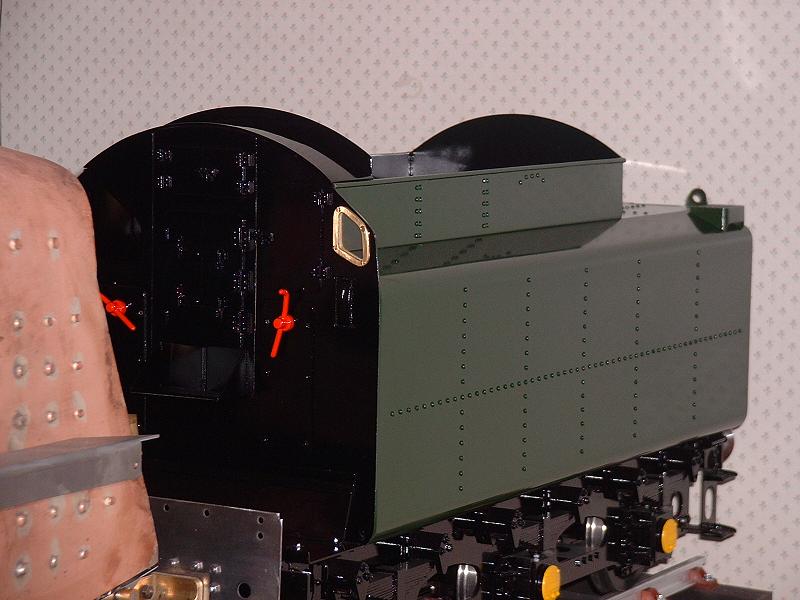
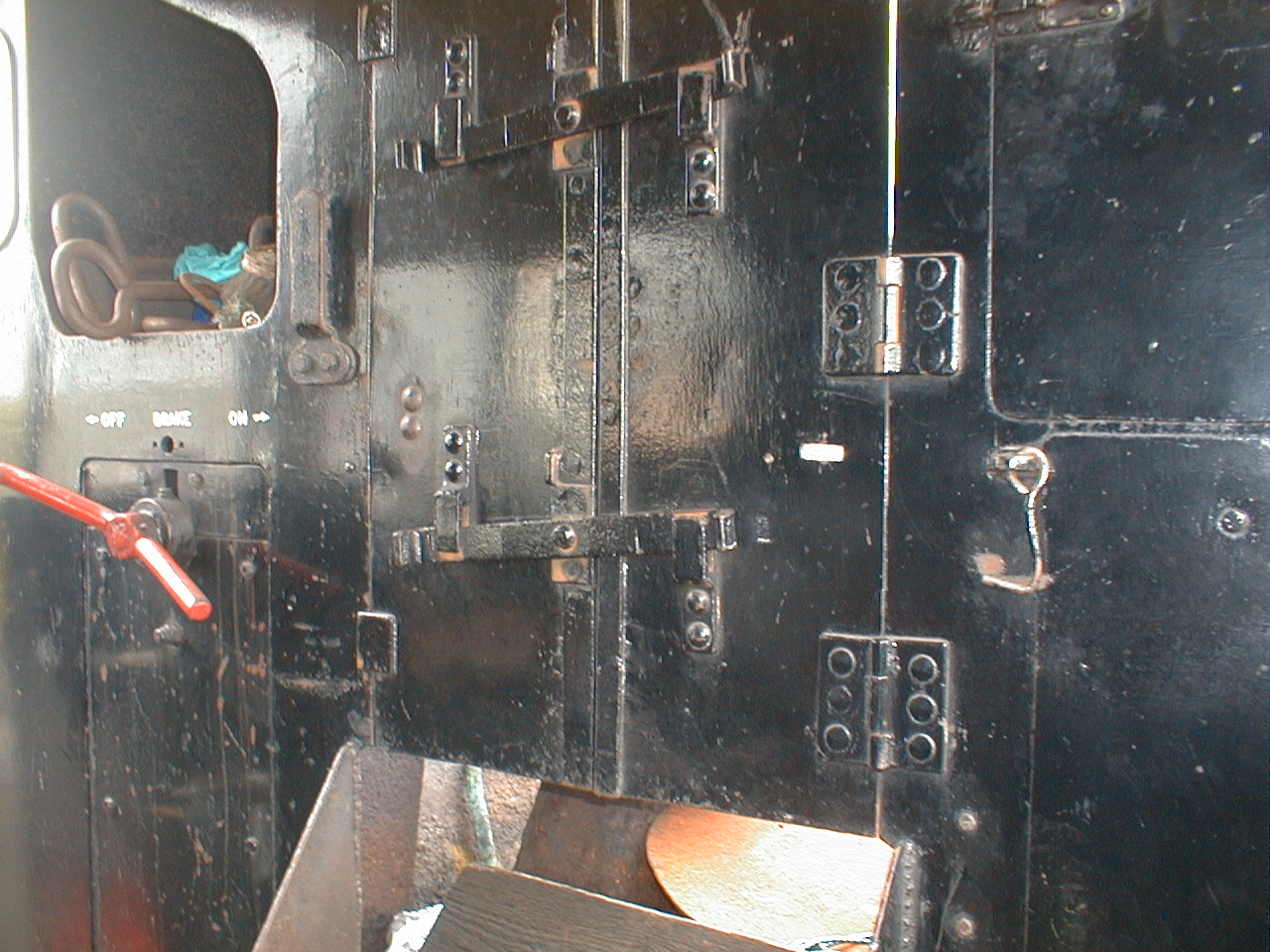
11/7/07 I've finished painting the black parts of the tender, as shown in this photograph. The glossy black enamel doesn't show the detail very well under the flashlight - the picture of the unpainted tender earlier on this page taken on 15/2/06 shows the detail better. I shall either scrape the water gauge to a brass finish or paint it red, depending on how 70013 is restored - currently it has a brass gauge, but 70000 has a red one. I now just need to put some finishing coats on the green parts.
 22/3/08
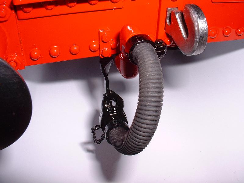
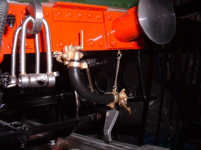
I've fitted the tender guard irons supplied in kit 18b, and also fitted the carriage heating hose that I bought from Doug Hewson. I bolted a small brass bracket to the underside of the rear beam and tapped an M3 stud into the casting to secure it after cutting off the much larger thread on the rear of the casting. The end of the hose is secured by its chain to an eye fitted under the buffer.
22/3/08
I've fitted the tender guard irons supplied in kit 18b, and also fitted the carriage heating hose that I bought from Doug Hewson. I bolted a small brass bracket to the underside of the rear beam and tapped an M3 stud into the casting to secure it after cutting off the much larger thread on the rear of the casting. The end of the hose is secured by its chain to an eye fitted under the buffer.
16/5/08 Modelworks have supplied two additional feed pipes in kit 18c, so that we can have four separate feeds for the handpump, axlepump and each injector, along with the return feed from the axlepump bypass. They haven't provided two additional filters, so I plan to use the two existing filters on the injector feeds since the injectors are presumably more susceptible than the pumps to blockage from debris in the tank. There is no provision for supporting the front ends of the pipes under the tender front beam, so I shall use a short piece of brass angle on each side with screws tapped into the underside of the cast iron front stretcher, drilled to take the 3/16" feed pipes - the left-hand injector and the axlepump on the left, and the right-hand injector, the handpump and the axlepump bypass return on the right.
 7/6/08
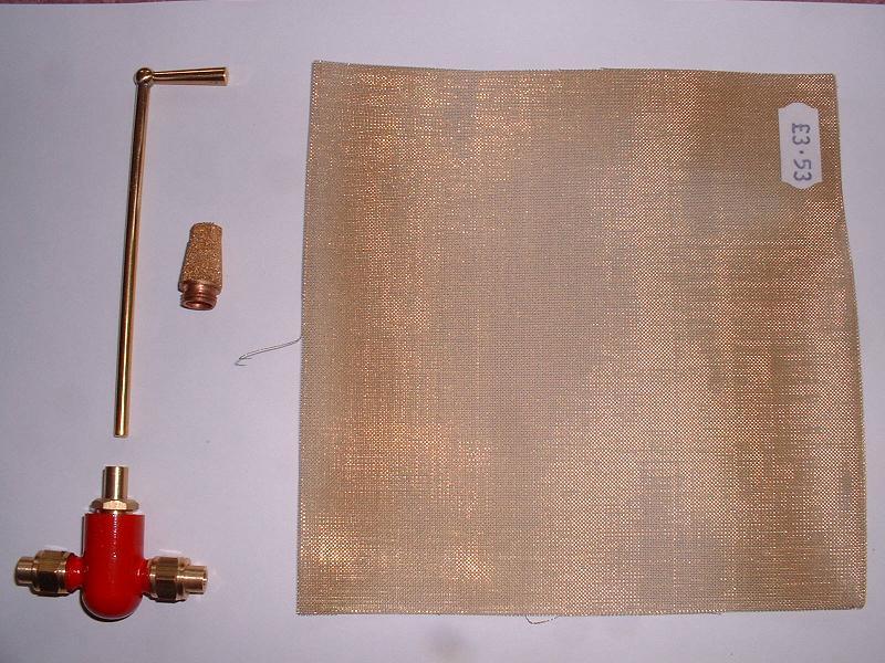
I'm about to start work on the tender pipework. I've bought two water valves to fit inside the tender for the injector feeds. These come from Polly and have a 90 degree on-off action and an unrestricted delivery when fully open. They will be more convenient to operate than valves in the cab, and the handles give an immediate indication of whether the valve is
open or closed. The handles are not long enough to extend right up through the rear top plate, so I'll drive with the plate off to start with and decide whether to extend them later. I've been told that the two water filters supplied in kit 4 and pictured here are not very practical - they are made from sintered metal particles and designed as silencers for pneumatic fittings. They apparently clog easily, and are then difficult to clean. I've therefore bought a 6" square of brass gauze from Blackgates and will use this to make four new filters for the four delivery pipes.
7/6/08
I'm about to start work on the tender pipework. I've bought two water valves to fit inside the tender for the injector feeds. These come from Polly and have a 90 degree on-off action and an unrestricted delivery when fully open. They will be more convenient to operate than valves in the cab, and the handles give an immediate indication of whether the valve is
open or closed. The handles are not long enough to extend right up through the rear top plate, so I'll drive with the plate off to start with and decide whether to extend them later. I've been told that the two water filters supplied in kit 4 and pictured here are not very practical - they are made from sintered metal particles and designed as silencers for pneumatic fittings. They apparently clog easily, and are then difficult to clean. I've therefore bought a 6" square of brass gauze from Blackgates and will use this to make four new filters for the four delivery pipes.
21/6/08 I've made the first of the new water filters - I cut two end pieces from 8mm brass rod, drilled one of them and soldered it onto the end of the copper pipe, and then rolled a piece of the brass gauze about 35mm long around a pencil to the right diameter with a small overlap, tinned the end pieces, clipped the gauze over them and soldered it to the end pieces and along the seam. I've worked out the position for the new injector feeds and valves - I'll drill new 8mm holes in the tender base in front of both the tank bulkhead and the frame stretcher and take short pipes from the tank fittings back through the bulkhead to the valves, which will be secured by brackets on either side of the handpump pedestal. The filters will lie behind the valves near the base of the tank. Incidentally all the tank fittings - the three supplied in kit 4 and the two extra in kit 18c - had very constricted passages of about 2mm, and so I drilled these out to 3mm to match the inside pipe diameter.
 25/6/08
I've attached brass angle strips to each side of the handpump pedestal to support the water valves - I made these from the superfluous front tender handrail brackets. I soldered plates over the two front water feed holes in the base of the tender, which clash with my water valves, and I'll make four new holes for all the pipes apart from the handpump feed, which remains in its original position. I'll bring the axlepump return back to the left hand side, since my rearranged pipework for the bypass valve exits on the left of the loco.
25/6/08
I've attached brass angle strips to each side of the handpump pedestal to support the water valves - I made these from the superfluous front tender handrail brackets. I soldered plates over the two front water feed holes in the base of the tender, which clash with my water valves, and I'll make four new holes for all the pipes apart from the handpump feed, which remains in its original position. I'll bring the axlepump return back to the left hand side, since my rearranged pipework for the bypass valve exits on the left of the loco.
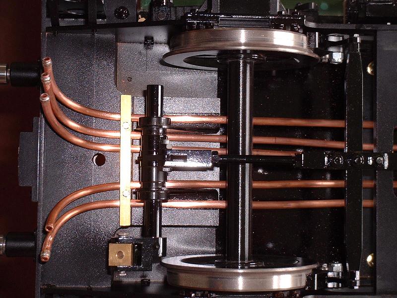
2/7/08 Just back from a few days sailing in a hot and sunny Solent, with wind and tides behind us all the way. I've completed the internal pipework and the photo now shows the final arrangement. The next job is to bolt the tender body to the chassis and check for leaks, then fit the pipes under the body.
5/7/08 I've bolted the tender body to the chassis - this is the first time that I've done this properly, and I found that I had to open out the holes in the rear stretcher to align them with the threads in the angle across the rear of the tank. I've also fitted the five pipes under the tank, securing them with a notched strip of 1/4"x1/16" brass angle bolted into holes tapped M3 in the underside of the cast iron front drag box. I now just need to bend and trim the front ends of the pipes and fit the flexible hoses.
 7/7/08
The photo shows the completed pipework, with collars soldered on four of the pipes to hold the 3/16" flexible hoses. The fifth pipe is for the 11mm x 5mm handpump pressure hose, which will be held by the hose clamps supplied with it in kit 18a. The next and pretty much final job prior to the steam test is to construct the rolling road.
7/7/08
The photo shows the completed pipework, with collars soldered on four of the pipes to hold the 3/16" flexible hoses. The fifth pipe is for the 11mm x 5mm handpump pressure hose, which will be held by the hose clamps supplied with it in kit 18a. The next and pretty much final job prior to the steam test is to construct the rolling road.
| Next Kit | Previous Kit | Index |