 22/11/05
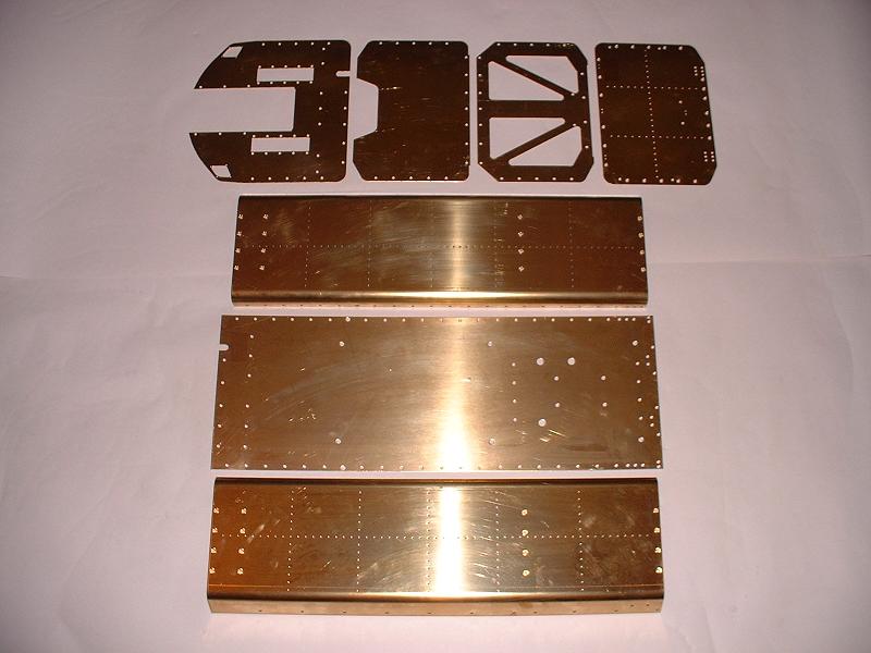
Kit 3 arrived at 10am. It contains the wheels held over from kit 2, together with much of the brasswork for the tender body, and the handbrake actuator mechanism. I checked and photographed the contents, which all seem present and correct.
22/11/05
Kit 3 arrived at 10am. It contains the wheels held over from kit 2, together with much of the brasswork for the tender body, and the handbrake actuator mechanism. I checked and photographed the contents, which all seem present and correct.21/11/05 I ordered kit 3 this morning.
22/11/05
Kit 3 arrived at 10am. It contains the wheels held over from kit 2, together with much of the brasswork for the tender body, and the handbrake actuator mechanism. I checked and photographed the contents, which all seem present and correct.
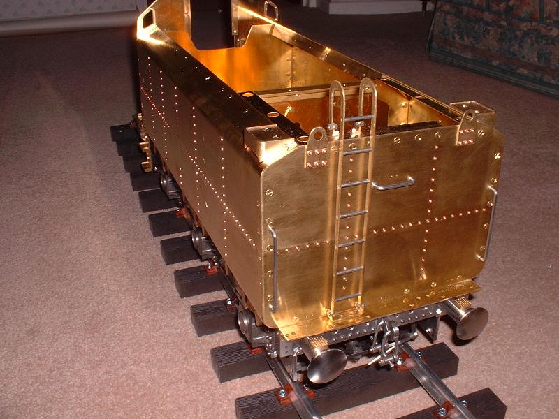
23/11/05 I fixed the tender wheels to the axles with Loctite, reinstalled the axles and adjusted the brakes, which seem to pull reasonably evenly against the three pairs of wheels. The chassis sits nicely on its wheels, and the springs do not deform noticeably despite the substantial weight of the tender - now standing at 45lb, including the brasswork for the body. I shall need to think carefully about how many improvements to make to the standard kit during the assembly of the tender body. At a minimum some of the bolts need to be replaced by countersunk screws or rivets. I've obtained a catalogue of optional extra parts from Doug Hewson, including items such as more accurate front and rear tender steps. I need to decide whether to aim for the greatest possible accuracy or simply to build a good well-painted working model. Striving for total accuracy looks expensive in both time and money!
24/11/05 I started on the brasswork of the tender body. The parts are beautifully cut and shaped - they just need a small amount of cleaning up with a file to remove the small regular bumps along the edges left by the cutting machine. I bolted the angles to the edges of the four bulkheads, and then loosely bolted the bulkheads to the baseplate and the tender sides, just to check how it all fits together. It looks very good, and only a small amount of filing and filling will be needed to get a perfect joint at the corners. I received the book 'The Finishing Touch' today from Phoenix Precision Paints, so I can now start to decide how to tackle this important part of the project.
25/11/05 I visited Chronos in Dunstable to buy a 1/16" rivet snap for the 300-odd decorative rivets on the tender sides and rear - Modelworks suggest glueing or soldering them in, but proper rivetting is just as quick and more satisfying. I also bought a set of M3 taps to sort out a few missing or short screw threads, a 6.2mm countersink to convert some of the bolt fixings to countersunk screws, and some 3/32" copper rivets for the lifting lugs on the rear of the tender. Chronos were having an open day with 10% off to celebrate their new premises, so they were quite crowded - there was even a 4" scale traction engine raising steam outside the front door. Not a Modelworks Burrell, unfortunately.
 26/11/05
I started on the rivetting - just a matter of snipping each rivet down to 1/8" long, supporting the head in the rivet snap and gently hammering the tail down onto the inside surface. It took about 2 hours to do the 50 rivets on the rear panel of the tender. I spotted that the full-size tender has no rivets on the centre of each side panel where the BR logo is positioned - see here - so I shall fill these holes in. Incidentally 70000 has different BR logos on the two sides of the tender - see here for the other side! I rivetted the two lifting lugs to the top of the rear panel, using 3/32" copper rivets. I fixed the upper handrail - the threaded ends are clamped between two thin M3 nuts on the outside and inside of the rear panel, but I turned the flats off the outer nuts (using an electric drill and Dremel grinding wheel - I don't have a lathe) so that they form thin round collars. The threads on this handrail were very short and I had to countersink the inside of the holes to expose enough thread for the nut to grip on. The other handrails look OK.
26/11/05
I started on the rivetting - just a matter of snipping each rivet down to 1/8" long, supporting the head in the rivet snap and gently hammering the tail down onto the inside surface. It took about 2 hours to do the 50 rivets on the rear panel of the tender. I spotted that the full-size tender has no rivets on the centre of each side panel where the BR logo is positioned - see here - so I shall fill these holes in. Incidentally 70000 has different BR logos on the two sides of the tender - see here for the other side! I rivetted the two lifting lugs to the top of the rear panel, using 3/32" copper rivets. I fixed the upper handrail - the threaded ends are clamped between two thin M3 nuts on the outside and inside of the rear panel, but I turned the flats off the outer nuts (using an electric drill and Dremel grinding wheel - I don't have a lathe) so that they form thin round collars. The threads on this handrail were very short and I had to countersink the inside of the holes to expose enough thread for the nut to grip on. The other handrails look OK.
27/11/05 Having observed yesterday that the tender of 70000 'Britannia' has no rivets under the tender logo, Richard alerted me to photographs of 70013 'Oliver Cromwell' which clearly does have these rivets - see here! I'm confused now - I think I'll leave them out anyway, since I can't see how the logo transfer would fit over the rivet heads. Anyway, enough of this rivetting conversation - I must get on with the tender body. I fitted one of the steps at the top rear of the tender side - these need adjustment to sit higher up, rather than overhanging the tender side. The picture shows the correct positioning. I filed one of the steps and drilled new fixing holes in the tender side about 1/4" above the existing ones.
28/11/05 I filed and fitted the other tender step. The steps really need a chequer-plate infill in the tread, and Richard tells me that this can be bought from Blackgates Engineering, so I shall probably order some in due course, along with half-round brass beading for the top of the coal bunker. I've decided to use countersunk brass screws rather than the bolts supplied all along the top and bottom of the tender sides - the bolts would look rather ugly, and I can't understand why Modelworks countersunk some but not all of the fixings on the tender bodywork. So the next job is to countersink about 60 holes. I could have rivetted the bottom edges, but it looks rather fiddly to do this because the inward curve on the top of the sides would get in the way of the hammer. Also the rivets would have to be rather large to fill the M3 holes. I've also decided that an extra fixing bracket is needed between the top rear corner of each side and the rear panel, just outside each lifting lug. Although the brass is very stiff, I think there's a risk that the joint will move and the paintwork will crack without this extra support.
29/11/05 I did the countersinking along the top of the sides and the baseplate side joints, then did another trial assembly and adjusted a few edges to get a good fit. I then put the decorative rivets in one of the tender sides, leaving space at the centre for the BR logo. Fortunately only three of the rivets clashed with internal fittings and had to be filed flat in countersunk holes - the rest are just hammered down and left slightly proud of the inner surface. I was alerted by Richard (this is another Richard, who is just starting on the Modelworks Britannia) to a website describing a scratch build of a 7 1/4" Britannia, and I've ordered BR Standard Britannia Pacifics, one of the books it mentions, secondhand via Amazon.
30/11/05 I put the rivets in the other tender side, and started to look at the tender ladder. Its fixing brackets and bolts are rather too large, so I'll buy some 1/16" x 1/4" brass strip and some 8 or 10BA bolts to make up some new ones. In the meantime I fixed the spectacle plates that surround the little windows in each side of the front bulkhead. One of these was slightly lop-sided so I re-drilled three of the fixing holes to get it vertical. I plan to leave these spectacle plates in polished brass - at least on the forward-facing side - so I shall fit them permanently along with perspex windows after the tender is painted.
1/12/05 I fitted the two vertical handrails to the rear bulkhead, turning the flats off the outer nuts as before. I assembled the ladder, using Loctite to fix the rungs into the siderails - a purist would have soldered them, but Loctite certainly gives a neater and probably stronger result than I for one could achieve with solder. I also ordered a 2.5m length of display track from PNP Railways.
2/12/05 I made my weekly pilgrimage to Chronos to buy a Clarke 5-speed bench drill (Ł35) and a Badger 200-3 airbrush set (Ł53) - both excellent value - together with the brass strip and nuts and bolts (6BA but with small 4.3mm heads and nuts) to fix the tender ladder.
 3/12/05
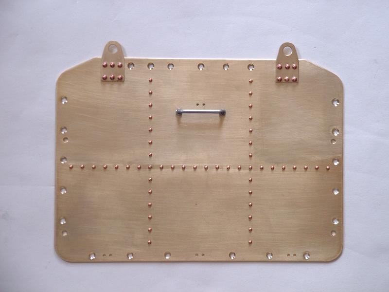
I completed and fitted the tender ladder - in the end I was able to file down the brackets supplied to a realistic size rather than making new ones. It looks much better with the small-headed nuts and bolts. I assembled the handbrake mechanism, shown in this photograph. This consists of a handle and spindle on the front bulkhead driving a pair of bevel gears in a brass housing behind the front bulkhead, turning a vertical shaft with a threaded lower end that moves the arm of the braking mechanism already installed as part of kit 2. It took some filing of the gear housing to get the gears to turn freely. The spindle is not long enough to go right through the gear and into the hole in the back of the housing without the handle catching against the front panel, so the gear movement is a little bit rough. I shall look into getting a longer spindle. The book 'BR Standard Britannia Pacifics' arrived this morning - it has nearly 100 pages of black-and-white photographs of Britannias, including many of 70013 'Oliver Cromwell' on which this model is based, and should provide some useful points of detail.
3/12/05
I completed and fitted the tender ladder - in the end I was able to file down the brackets supplied to a realistic size rather than making new ones. It looks much better with the small-headed nuts and bolts. I assembled the handbrake mechanism, shown in this photograph. This consists of a handle and spindle on the front bulkhead driving a pair of bevel gears in a brass housing behind the front bulkhead, turning a vertical shaft with a threaded lower end that moves the arm of the braking mechanism already installed as part of kit 2. It took some filing of the gear housing to get the gears to turn freely. The spindle is not long enough to go right through the gear and into the hole in the back of the housing without the handle catching against the front panel, so the gear movement is a little bit rough. I shall look into getting a longer spindle. The book 'BR Standard Britannia Pacifics' arrived this morning - it has nearly 100 pages of black-and-white photographs of Britannias, including many of 70013 'Oliver Cromwell' on which this model is based, and should provide some useful points of detail.
4/12/05 I started fitting the details on the front bulkhead - the strip across the top of the tender platform angle, and the slides on either side of the central cutout (I assume that the removable piece that slots in there is to facilitate access to the controls when driving). I'm using countersunk screws or small-headed bolts in place of the M3 bolts supplied, depending on whether the real tender has bolts in the corresponding places. I fitted the front steps, although I shall probably replace them with Doug Hewson's version.
5/12/05 I fitted the two plates that carry the handbrake and water pick-up handles, just using 3 small bolts on each side of each plate to match the real tender. I'll fill in the superfluous holes later before painting. I fitted the guard plates and handrails to the sides of the front bulkhead, although I haven't yet established for certain that 70013 has these - 70000 does not, and if 70013 has them they are obscured by the rubber weathershield fitted between the cab and tender. I bolted the tender body to the chassis, and adjusted the brakes. This more or less completes kit 3, although I am still awaiting an extra supply of M3 countersunk screws to finish bolting up the sideplates, and I need to improve the handbrake spindle and fit my extra brackets in the top rear corners. I ordered kit 4 this afternoon - it should arrive on 7 December.
 6/12/05
The 2.5m display track kit arrived from PNP Railways - I assembled this and trimmed it down to 75" long, which is an inch shorter than my workbench and an inch longer (hopefully) than the finished model. My wife caught me rolling the tender backwards and forwards along the track, which convinced her (if any convincing were needed) that I have finally regressed to my second childhood.
6/12/05
The 2.5m display track kit arrived from PNP Railways - I assembled this and trimmed it down to 75" long, which is an inch shorter than my workbench and an inch longer (hopefully) than the finished model. My wife caught me rolling the tender backwards and forwards along the track, which convinced her (if any convincing were needed) that I have finally regressed to my second childhood.
7/12/05 No sign of kit 4 today, but the M3 countersunk screws arrived and I completed the bolting up, including fitting the extra bracket in one of the top rear corners, which stiffened the joint nicely.
8/12/05 Kit 4 arrived this afternoon. I ordered the improved tender steps from Doug Hewson, who told me in passing that the rear ladder has one rung too many at the top, and he's quite right - pity I didn't spot that before I glued it together last week!
| Next Kit | Previous Kit | Index |