 11/11/05
Kit 2 arrived at 8am. I checked the contents and put it aside pending completion of kit 1.
11/11/05
Kit 2 arrived at 8am. I checked the contents and put it aside pending completion of kit 1.
11/11/05
Kit 2 arrived at 8am. I checked the contents and put it aside pending completion of kit 1.
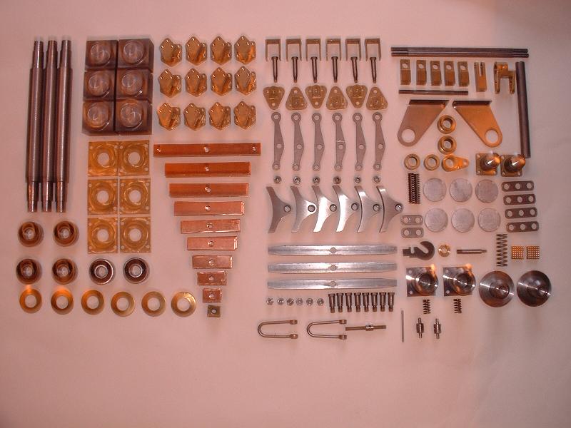
12/11/05 The kit contains a complete set of steel spring leaves as well as the bronze ones shown in the photograph. This allows the strength of the springs to be adjusted when the model has been completed, by mixing steel and bronze leaves as required. Modelworks intended to include the tender wheels in kit 2, but the quality of the castings was sub-standard so they were recast and included in kit 3. Although I am starting my build a year late, the kits that I am being sent were packed at the time of manufacture.
13/11/05 I started to fit the axle boxes between the horn cheeks and discovered that the cheeks had not been milled square - they were 0.6 mm further apart at the outside edge than the inside edge. My first reaction was to send them back - and I'm sure Modelworks would have fixed or replaced them - but I managed to square up one pair by clamping them face to face and carefully filing them. This took about half an hour. The result was parallel to within 0.02mm - very satisfying. I shall tackle the other five pairs tomorrow.
14/11/05 I filed another pair of horn cheeks and assembled one axle with bearings and axle boxes - it turns and slides up and down very smoothly. One screw hole in one of the axle boxes is not threaded, so I shall need to acquire a set of M3 taps. I could return the part to Modelworks, but I'll need the taps sooner or later anyway. I also did a trial assembly of one set of springs and spring hangers, to check the riding height of the axle box. I need to clarify whether there should be 10 or 11 leaves on each spring - the instructions are ambiguous on this point. It looks as though even with 11 leaves I shall need to bend the springs slightly in order to get the axle box riding at the mid-point of its travel, but I'll probably wait until I have the tender built and fully laden before doing so. Richard tells me that he has used 11 leaves, and bent the springs, and fitted a brass spacer between the springs and the axle box. I also ordered the book 'The Finishing Touch' from Phoenix Precision Paints, to help me decide how and when to paint the model. They seem to be getting back into business after the factory fire, now on 01268 730549.
16/11/05 I filed the remaining horn cheeks and assembled the other two axles, and bolted on the rest of the spring hangers and brake hangers. I fitted the springs, using 9 bronze leaves sandwiched between the largest and smallest steel leaves to give 11 leaves in all. The axle boxes ride fairly high in the horn cheeks with this arrangement. One thing I might try is to assemble the shackle the other way up, with the bolt head under the springs packed out with washers or a spacer so that the top of the bolt thread is just flush with the top of the shackle. This would lower the axle boxes by the thickness of the bolt head, and look more realistic since the real Britannia does not have a bolt on the top of the shackle - see this picture.
17/11/05 I assembled the brake shaft that transmits the handbrake motion to the brake stretchers and shoes. It's difficult to align the bearings for this shaft since they are carried in bent steel plates rather than properly machined blocks, so the movement is a bit stiff. I'm also not convinced that the grub screws on the two lever arms will be strong enough to avoid the mechanism slipping under strain. We shall see.
18/11/05 I assembled the rest of the tender brake gear - it went together very easily. The nyloc nuts holding the brake shoes to the brake hangers look rather incongruous - I might replace them with plain nuts secured with Loctite. The brake pull rod ends were a sloppy fit between the brake connecting plates, allowing the pull rods to flop from side to side, but I fixed this by using washers to clamp the pull rod ends tightly between the upper and lower connecting plates, still leaving the brake stretchers free to rotate between the connecting plates and hence balancing the brake pressure on opposite sides. I can't adjust the pull rod lengths until I get the tender wheels in kit 3. I rather expected the adjustable pull rod connecting the front brake stretcher to the brake shaft lever arm to have left and right handed threads like a bottlescrew, but it doesn't, so it will be necessary to disconnect one end in order to adjust the length. However, this is no great hardship - if it had not been advertised as 'adjustable', I'd never have noticed.
 19/11/05
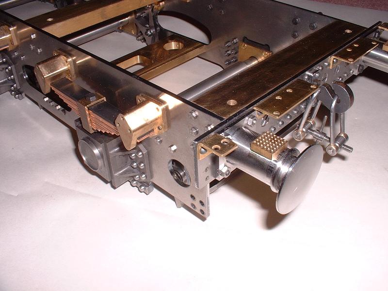
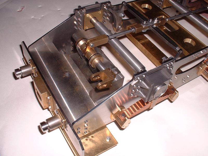
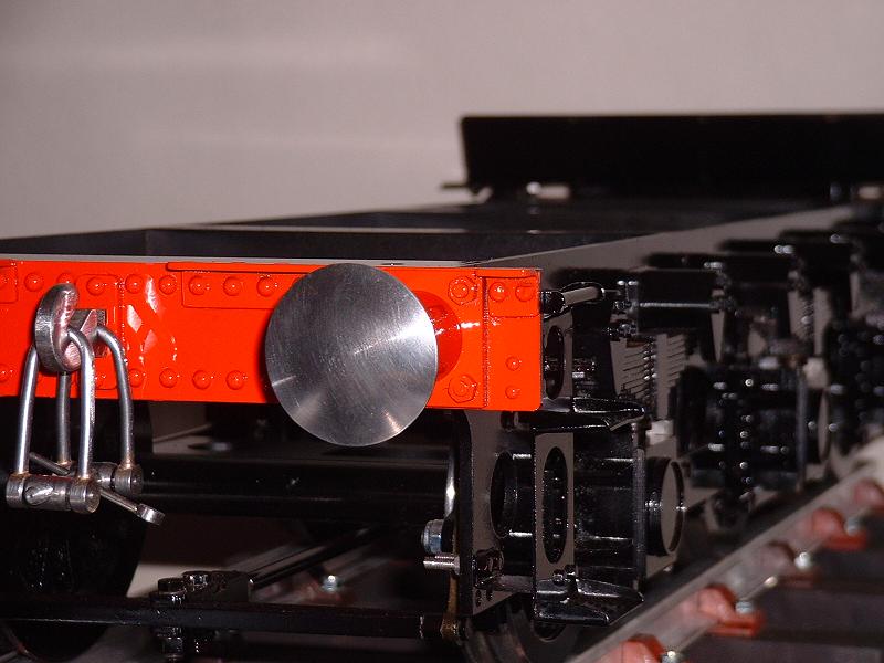
I fitted the buffers, draw hook and coupling links today, thus completing kit 2. I fitted the buffer bolts with the nuts on the outside, which is the full-size practice - see this picture - even though the standard M3 nuts are somewhat oversize. The pictures show the front underside with the braking mechanism, and the rear end with springs, buffers and draw hook. I have not yet glued the aluminium Timken bearing covers on to the axle boxes, to avoid scratching them.
19/11/05
I fitted the buffers, draw hook and coupling links today, thus completing kit 2. I fitted the buffer bolts with the nuts on the outside, which is the full-size practice - see this picture - even though the standard M3 nuts are somewhat oversize. The pictures show the front underside with the braking mechanism, and the rear end with springs, buffers and draw hook. I have not yet glued the aluminium Timken bearing covers on to the axle boxes, to avoid scratching them.
18/8/06 I can't do any more work on the locomotive until I get the redrilled smokebox and/or corrected motion and/or the boiler, so I'll continue with the tender chassis. Today I fitted studs and nuts to the 36 holes in the spring hangers. I thought that M3 studs and nuts to fit the tapped holes would look far too large (and no studs and nuts were included in the kit), so I snipped the heads off 8BA brass screws and glued them into the holes with Araldite and fitted 8BA brass nuts.
19/8/06 I cut to length and fitted 24 small-headed 6BA bolts to the hornblock stays - these are more accurate than the rivet-head bolts supplied (see kit 1, 6/11/05).
20/8/06 I've decided to paint the tender chassis next, so I dismantled the wheels and axleboxes, brakes, steps, springs, front platform and buffers. I then draw-filed the edges of the frames, which I'd omitted to do in my rush to build the first kit, and filled the heads of the countersunk screws in the buffer beams.
 23/8/06
I decided to put Loctite 243 Nutlock on all the nuts and bolts on the frames to stop them working loose. This took some time - there are 84 on the hornblocks alone. I removed them one at a time to preserve the alignment. I masked up the hornblock slides and started to clean the chassis down with cellulose thinners in preparation for etch priming.
23/8/06
I decided to put Loctite 243 Nutlock on all the nuts and bolts on the frames to stop them working loose. This took some time - there are 84 on the hornblocks alone. I removed them one at a time to preserve the alignment. I masked up the hornblock slides and started to clean the chassis down with cellulose thinners in preparation for etch priming.
24/8/06 I etch-primed the chassis, covering all of it - brass, steel and cast iron - with a thin coat of two-part etch primer, sprayed on with the airbrush at a low pressure of about 15psi and with the airbrush about 2-3 inches from the surface. This seemed to work quite nicely.
26/8/06 I've sprayed the black enamel onto the chassis, applying several thin coats in a single session to give a nice gloss finish. I used a pressure of about 35psi and diluted the enamel about 75:25 with quick air drying thinners. There's just one sag on the front buffer that will need rubbing down and respraying. I've started masking up the wheels and other parts in preparation for etch-priming.
28/8/06 I've now etch-primed and painted the axleboxes, steps, front platform and brake gear, leaving just the wheels and springs to be done before I can re-assemble the tender chassis. I decided not to dismantle the springs into their individual leaves for painting, since they will stay tight together under compression and so the bare metal should not be visible. I did however run the tip of a file along the joins to make the individual leaves more prominent.
30/8/06 I've etched-primed the wheels and springs, and the Timken bearing covers. I removed the paint from the front platform and etch-primed it again, because there was a sag that I couldn't sand out without exposing bare brass around it. The countersunk screws that I filled on the rear buffer beam were showing slight indentations with the light shining on the black gloss - the gloss paint shows such imperfections much more than the matt primer - so I filled these again with Holt's Knifing Putty. It's a shame that the buffer beam has these large fixings - it's quite tricky to sand the filler down flat in among the rivets, and the front buffer will be even trickier. I'll overcoat the rear buffer in red gloss at a later stage.
1/9/06 I've continued painting the wheels and springs. I'm taking more care to prevent dust settling on the paint, by placing the parts under an upturned plastic box immediately after painting.
 3/9/06
I've now finished all the black paint on the chassis components, apart from a final coat on the front platform after I've re-assembled it. I'm pretty happy with the finish now - airbrushing certainly takes lots of practice. Even the buffer beam now looks pretty good after several cycles of filling, sanding and painting, and ready for its final coats of signal red. We're now off to the boat for a few days, after which I'll re-assemble the chassis, paint the buffer beam and paint and fit the Timken bearing covers.
3/9/06
I've now finished all the black paint on the chassis components, apart from a final coat on the front platform after I've re-assembled it. I'm pretty happy with the finish now - airbrushing certainly takes lots of practice. Even the buffer beam now looks pretty good after several cycles of filling, sanding and painting, and ready for its final coats of signal red. We're now off to the boat for a few days, after which I'll re-assemble the chassis, paint the buffer beam and paint and fit the Timken bearing covers.
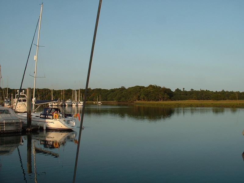
7/9/06 Just back from 3 days sailing from Lymington to Portsmouth and then back via Buckler's Hard, pictured, on the Beaulieu river - perfect sailing weather, hot and sunny and a good breeze. I've refitted the springs, axles and horn stays to the tender chassis. This afternoon I went along to the North London SME track near St Albans and spent a few hours learning to raise steam and drive the club loco, a 0-6-0 'Butch' tank engine, under Derek's expert guidance. I managed to tend the fire while on the move, and use the axle pump and injector to keep the water level up.
9/9/06 I've refitted the brake gear, and put a final coat of paint on the front platform and refitted it to the chassis along with the front steps. I now just need to touch in the bolt heads with a brush.
13/9/06 Back from another few days sailing, enjoying the late season sunshine - we got right up to Newport at the centre of the Isle of Wight on the top of the spring tide. I've touched in the bolt heads with primer and will spray the buffer beam red. Still no news from Modelworks about my boiler or smokebox drilling or revised motion gear.
 15/9/06
I've painted the bolt heads black and sprayed the buffer beam red, although there's one conspicuous speck of dust so I'll need to rub this out and give it a final coat tomorrow. One small question of detail is the colour of the edges of the buffer beams - the painting guide from Phoenix Paints says that these should be black, not red, so I've followed this advice, but the majority of the full-size locomotives that I've seen, including Oliver Cromwell and Britannia, have red edges to the buffer beams. It will be easy enough to touch them in with a brush if I can't persuade the restorers at Loughborough to change the prototype.
15/9/06
I've painted the bolt heads black and sprayed the buffer beam red, although there's one conspicuous speck of dust so I'll need to rub this out and give it a final coat tomorrow. One small question of detail is the colour of the edges of the buffer beams - the painting guide from Phoenix Paints says that these should be black, not red, so I've followed this advice, but the majority of the full-size locomotives that I've seen, including Oliver Cromwell and Britannia, have red edges to the buffer beams. It will be easy enough to touch them in with a brush if I can't persuade the restorers at Loughborough to change the prototype.
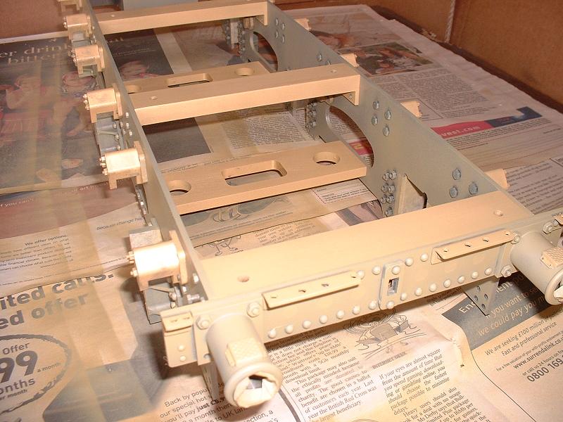
16/9/06 I've completed the painting of the tender chassis, as shown in this photograph. The Timken bearing covers still need to be painted and fitted. I'll next proceed to finish and paint the tender bodywork, which I'll describe under kit 4.
| Next Kit | Previous Kit | Index |