 1/2/07
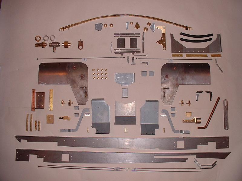
The first half of kit 18 arrived this morning. It contains the following items:
1/2/07
The first half of kit 18 arrived this morning. It contains the following items:
1/2/07
The first half of kit 18 arrived this morning. It contains the following items:
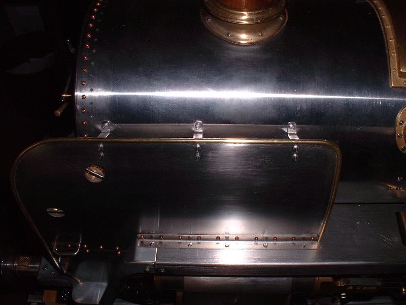
2/2/07 The first step in the instructions is to fit the lagging, but I don't intend to do this until I have the cladding - the lagging is pre-cut to shape and looks as though it will need only minor trimming, but it would seem safer to leave this until the cladding is available to check the fit. This leaves the platework and running boards as the first task. The smoke deflectors have been nicely made to the correct design for 70013, with two cutout handholds with cups brazed behind and two small handrails at the lower front, although they can't be fitted at this stage because their brackets have not been supplied yet.
 3/2/07
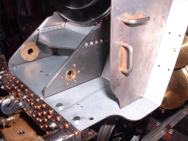
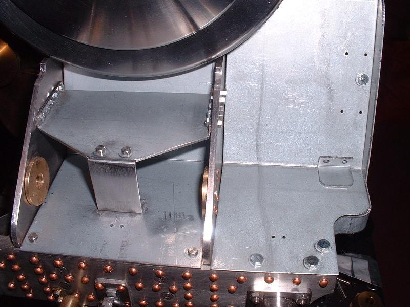
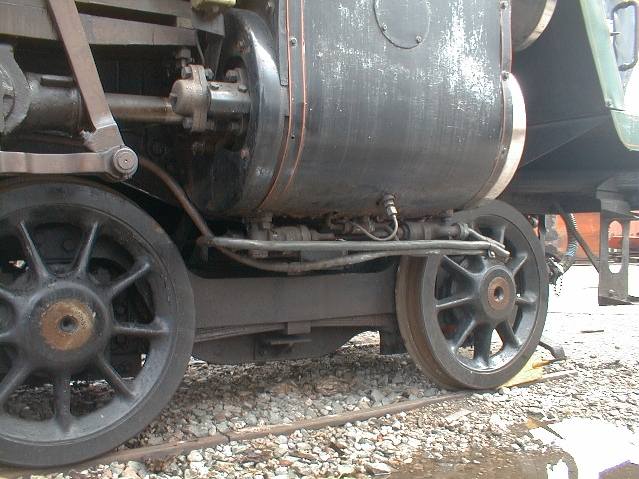
I've started on a trial fit of the left-hand running board and the left-hand and central front plates. The running board is supported by a bracket bolted to the frames between the driving and trailing wheels, and by the existing bracket on the lubricator mounting plate. It looks as though the lubricator bracket is a few mm too low and too far to the rear, and I'll need to adjust the lower bend in it to correct this. The front left plate is bolted to the buffer beam bracket and to the front of the running board - I had to increase the angle of the bend in it a little to match the angle of the smoke deflector and the outer trim, and file a little off the inner top edge to fit snugly against the smokebox. The central plate is bolted to the stretcher behind the buffer beam, and butts up under the smokebox - it just needed this edge filing a little to allow it to sit flat. The centre step fits between the frames and is held by five M2 bolts on each side - the holes in the step flanges are tapped for these. Although the instructions show the centre step fitted with the flanges on the underside, it should be the other way up as shown in this photograph of 70013. This will require the step support bracket to be shortened. I think it also looks better fitted in the rear four holes in the frames, so that it butts up to the angled front plate. The photograph shows it in this position - I've drilled two more holes, and will fill the front ones. The standard M3 bolts supplied to fix the platework look far too large and I'll order some small-headed ones (4mm across flats instead of 5.5mm) to replace them, as I did for the tender frames.
3/2/07
I've started on a trial fit of the left-hand running board and the left-hand and central front plates. The running board is supported by a bracket bolted to the frames between the driving and trailing wheels, and by the existing bracket on the lubricator mounting plate. It looks as though the lubricator bracket is a few mm too low and too far to the rear, and I'll need to adjust the lower bend in it to correct this. The front left plate is bolted to the buffer beam bracket and to the front of the running board - I had to increase the angle of the bend in it a little to match the angle of the smoke deflector and the outer trim, and file a little off the inner top edge to fit snugly against the smokebox. The central plate is bolted to the stretcher behind the buffer beam, and butts up under the smokebox - it just needed this edge filing a little to allow it to sit flat. The centre step fits between the frames and is held by five M2 bolts on each side - the holes in the step flanges are tapped for these. Although the instructions show the centre step fitted with the flanges on the underside, it should be the other way up as shown in this photograph of 70013. This will require the step support bracket to be shortened. I think it also looks better fitted in the rear four holes in the frames, so that it butts up to the angled front plate. The photograph shows it in this position - I've drilled two more holes, and will fill the front ones. The standard M3 bolts supplied to fix the platework look far too large and I'll order some small-headed ones (4mm across flats instead of 5.5mm) to replace them, as I did for the tender frames.
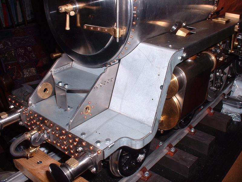
4/2/07 I've adapted the step support bracket to fit under the lowered front step. I think the top flanges of the front side plates will need adjusting slightly to fit the front ends of the running boards correctly, but I'm not inclined to do this until I have the final kit and can double-check the height and fore-aft position of the running boards against the cab platework and the smoke deflector brackets. I'll trial fit the side trim to the front plate next.
 5/2/07
The holes for the lamp iron in the centre plate were offset to line up with the optional lower lamp position on the smokebox door, but I've used the top centre position for that lamp, as on 70013, so I've drilled new holes in the centre of the plate to match. I've trial-fitted the side trim to the front plate - it is secured by two lugs to the front plate, and by a fishplate to the running board. The front lug will need adjusting slightly to fit snugly. The trim is not an ideal fit because the front end is under the front plate and it then comes out to be outside the angled rise, so there is a section where the two edges are exposed. I'll ponder how best to improve this - I could use filler to fair the joint, or I might make a new thinner trim that is on the outer edge of the front plate all the way along, and solder it to the plate to eliminate the lug behind the angled section which looks a little unsightly when viewed from the rear. One point to bear in mind here is that the outer plates and trims will need to be removed, along with the smoke deflectors, in order to adjust or remove the valves.
5/2/07
The holes for the lamp iron in the centre plate were offset to line up with the optional lower lamp position on the smokebox door, but I've used the top centre position for that lamp, as on 70013, so I've drilled new holes in the centre of the plate to match. I've trial-fitted the side trim to the front plate - it is secured by two lugs to the front plate, and by a fishplate to the running board. The front lug will need adjusting slightly to fit snugly. The trim is not an ideal fit because the front end is under the front plate and it then comes out to be outside the angled rise, so there is a section where the two edges are exposed. I'll ponder how best to improve this - I could use filler to fair the joint, or I might make a new thinner trim that is on the outer edge of the front plate all the way along, and solder it to the plate to eliminate the lug behind the angled section which looks a little unsightly when viewed from the rear. One point to bear in mind here is that the outer plates and trims will need to be removed, along with the smoke deflectors, in order to adjust or remove the valves.
6/2/07 I've filled the surplus holes in the central plate and frames with JB Weld. I've also adjusted the front lug on the side trim to give a good fit. I've decided to solder the trim to the front plate and remove the lug behind the rising section, and fair the exposed edge with solder or JB Weld. However, I won't do this until I have the next kit, to make sure that the platework is all correctly aligned. I've ordered 100 small-headed M3 bolts and 25 matching nuts, and some standard M2 nuts for the front step bolts, from Polly Model Engineering. I'm planning to fit half-round brass beading to the edges of the smoke deflectors - I'll try soft-soldering this to the steel plate.
7/2/07 I noticed that the brass cup behind one of the smoke deflector handholds had been fixed slightly off-centre, and one of the handrails had not been pushed right into one of its holes. I decided to try fixing these problems myself rather than returning them to Modelworks. I've never tried silver soldering before, but Jon M has kindly lent me a DVD on the subject which arrived this morning, so I watched that and then went off to Chronos and bought some Easyflo 2 silver solder and flux powder. I heated the brass cup and handrail red-hot with the gas torch to remove them, then cleaned up the joints, applied the flux mixed to a paste with water, clamped the cup in the correct position and inserted the handrail fully into its holes, and heated up the joints and touched the stick of silver solder on them. The result looks not at all bad for my first attempt at silver soldering, and feels rock solid.
 8/2/07
I started to fit 1/8" half-round brass beading to the edges of the smoke deflectors, as I did on the top of the tender coal bunker. This is not part of the kit, but should greatly improve the appearance. I annealed the beading to remove the springiness and allow it to be bent around the tight corners, by heating it to a dull red with the gas torch and allowing it to cool. It was then possible to bend it to match the tight 10mm radius at the top rear of the deflector without too much trouble - it tries to roll over, but with a little care can be pressed flat while easing it round the corner. I then started soft-soldering it to the steel, using Carr's Green Label flux (similar to Baker's Fluid), clamping each section with improvised clamps, heating it gently with the gas torch and touching thin solder wire into the joint. The solder flowed nicely into the joint leaving very little excess to be cleaned off, and this flux clearly works well on steel.
8/2/07
I started to fit 1/8" half-round brass beading to the edges of the smoke deflectors, as I did on the top of the tender coal bunker. This is not part of the kit, but should greatly improve the appearance. I annealed the beading to remove the springiness and allow it to be bent around the tight corners, by heating it to a dull red with the gas torch and allowing it to cool. It was then possible to bend it to match the tight 10mm radius at the top rear of the deflector without too much trouble - it tries to roll over, but with a little care can be pressed flat while easing it round the corner. I then started soft-soldering it to the steel, using Carr's Green Label flux (similar to Baker's Fluid), clamping each section with improvised clamps, heating it gently with the gas torch and touching thin solder wire into the joint. The solder flowed nicely into the joint leaving very little excess to be cleaned off, and this flux clearly works well on steel.
10/2/07 I've now completed soldering the beading onto the left-hand smoke deflector, and I'm pleased with the result. I need to order some more beading for the other smoke deflector, so I'll probably look at the firebox doors next.
 11/2/07
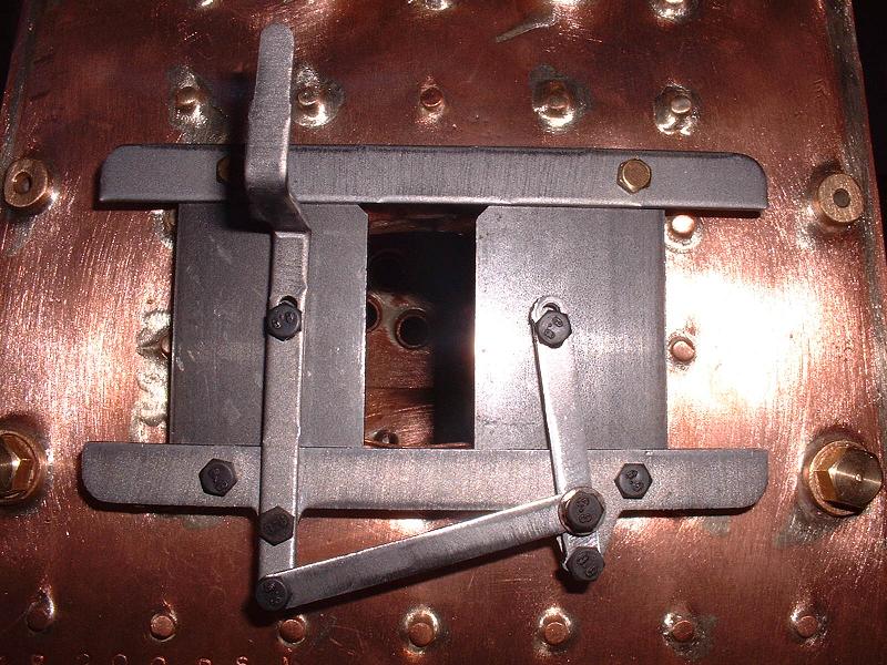
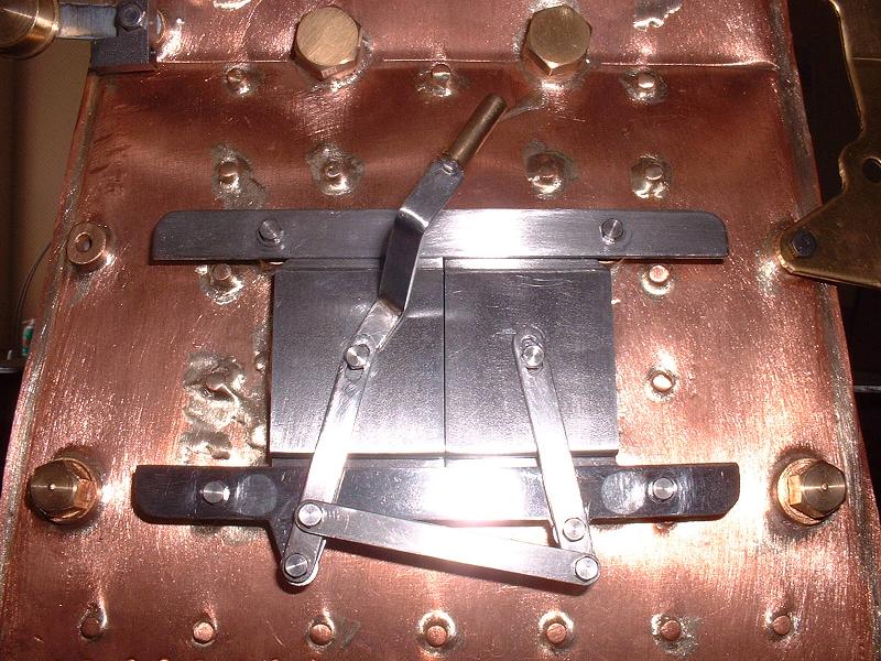
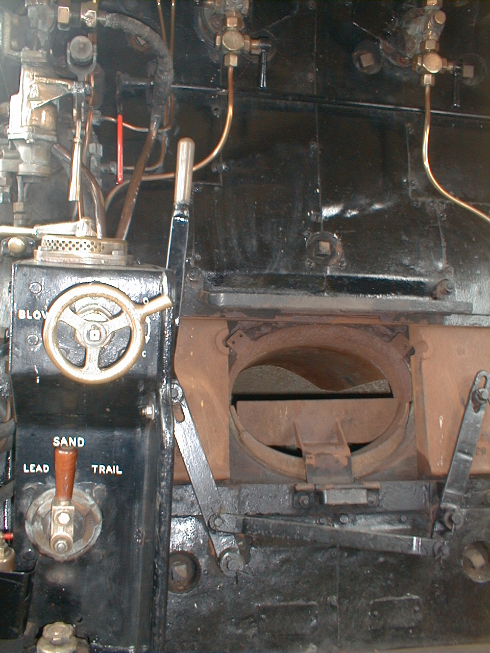
I've done a trial assembly of the firebox doors, as shown in the photograph. The photograph in the instructions is incorrect as it shows the handle on the right, and it should be on the left as shown here. This is presumably so that the driver can operate the doors while the fireman shovels the coal. I've changed the parts over to achieve this - this means that the countersinks on the lower slide are on the inside, but this doesn't matter since hex bolts don't interfere with the levers, and in fact they are closer to the prototype. I had to put washers on the slide mounting bushes as they didn't project quite as far as the lip of the firehole. The doors now slide reasonably smoothly, and should work well with a little further fettling and adjustment. However, the arrangement is still not quite correct since the connecting lever should be above the handle pivot and below the other pivot, and the left-hand pivot lug should be lower than the right hand one (ie the lower slide should revert to having its countersinks on the outside). This photograph of 70000 shows the correct arrangement of the levers. I'll think about whether to make up a new set of levers to this design. I won't fit the slides permanently at this stage, since I'm thinking of fabricating a brass cover for the boiler backhead, if Modelworks don't provide one in the final kit.
11/2/07
I've done a trial assembly of the firebox doors, as shown in the photograph. The photograph in the instructions is incorrect as it shows the handle on the right, and it should be on the left as shown here. This is presumably so that the driver can operate the doors while the fireman shovels the coal. I've changed the parts over to achieve this - this means that the countersinks on the lower slide are on the inside, but this doesn't matter since hex bolts don't interfere with the levers, and in fact they are closer to the prototype. I had to put washers on the slide mounting bushes as they didn't project quite as far as the lip of the firehole. The doors now slide reasonably smoothly, and should work well with a little further fettling and adjustment. However, the arrangement is still not quite correct since the connecting lever should be above the handle pivot and below the other pivot, and the left-hand pivot lug should be lower than the right hand one (ie the lower slide should revert to having its countersinks on the outside). This photograph of 70000 shows the correct arrangement of the levers. I'll think about whether to make up a new set of levers to this design. I won't fit the slides permanently at this stage, since I'm thinking of fabricating a brass cover for the boiler backhead, if Modelworks don't provide one in the final kit.
12/2/07 I've draw-filed the guard irons and fitted them to the front bogie, and trial fitted the dummy gauges and their brackets to the back of the firebox. I've also fitted the new drain cocks to the cylinders - these come in left and right hand versions, with the levers moving towards the rear on each side to open the valves. They have nuts and ferrules on the drains and I'll get some 3/32" copper tube to make the correct forward-facing exhausts, as shown here.
 14/2/07
The nuts and bolts arrived from Polly yesterday and I've started to cut them to length and fit them to the platework - the photo shows the contrast between the small M3 bolts in the centre plate and the standard ones in the side plate. I need to find a way of fixing the drain cocks into the cylinders at the correct orientation, either with thread locking compound or by using washers of the correct thickness - the threads are not long enough to take a locking nut. The holes in the drain cock operating levers are threaded 6BA, larger than the holes in the linkage rods, so I'll need to modify something here.
14/2/07
The nuts and bolts arrived from Polly yesterday and I've started to cut them to length and fit them to the platework - the photo shows the contrast between the small M3 bolts in the centre plate and the standard ones in the side plate. I need to find a way of fixing the drain cocks into the cylinders at the correct orientation, either with thread locking compound or by using washers of the correct thickness - the threads are not long enough to take a locking nut. The holes in the drain cock operating levers are threaded 6BA, larger than the holes in the linkage rods, so I'll need to modify something here.
16/2/07 Brian and Mick both emailed to say that Blackgates sell packs of copper washers of assorted thicknesses that can be used to lock the drain cocks (and other boiler fittings) at the correct orientation, so I'll order some of these. I've attached the drain cock links with 8BA steel bolts which fit snugly in the 6BA threaded holes of the drain cock levers. I tapped the links 8BA and fitted locknuts on the outside, but clearance holes and Loctite on the nuts would probably have served equally well.
 23/2/07
Just back from a short break in France, and I'm continuing to draw-file the edges of the platework and fit the small-headed bolts. I've asked Debbie when we can expect the second half of kit 18, but there's no firm news as yet.
23/2/07
Just back from a short break in France, and I'm continuing to draw-file the edges of the platework and fit the small-headed bolts. I've asked Debbie when we can expect the second half of kit 18, but there's no firm news as yet.
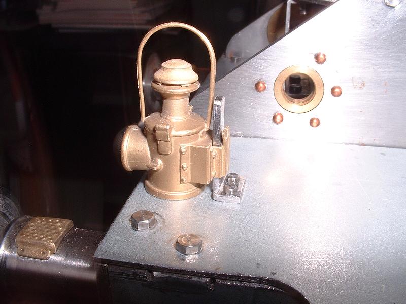
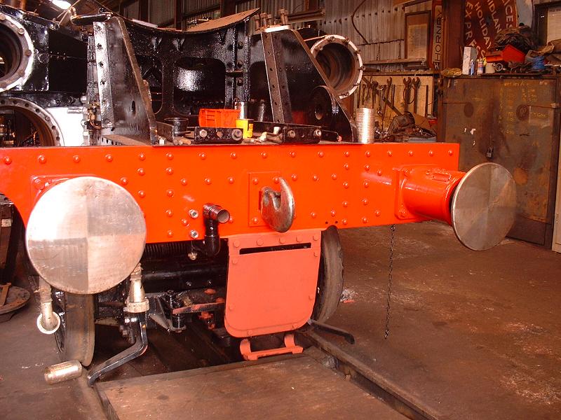
27/2/07 The brass lamp irons provided looked rather thin at 0.9mm compared with the 1.6mm of the tender and smokebox lamp irons, so I decided to make some new ones from 1.6mm steel strip. The photo shows the first one completed, along with one of the two superbly detailed lamps that I bought from the Miniature Railway Supply Co a year ago. Incidentally it's been pointed out that the rivets in the lifting rings in the frames should be flush on both sides, so I'll correct this when I dismantle for painting and can get a file to them. Update 3/4/07: I've now done this, while the buffer beam is removed for painting.
28/2/07 I've completed the three lamp irons. The beading, copper tubing and shim washers arrived from Blackgates today (I only ordered them two days ago) and I've started to bend the copper tubing to form the drain cock pipes.
 1/3/07
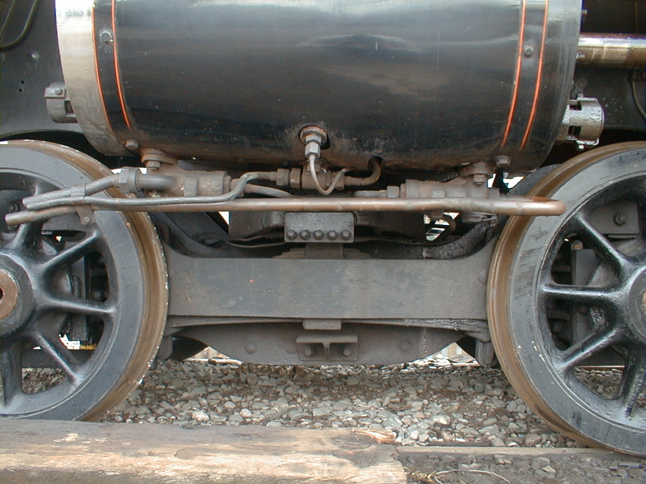
I've fitted the drain cock pipes, as shown in the photograph. I annealed the 3/32" copper tube to soften it, then bent the pipes to shape and soft-soldered the nipples on the ends. I then fitted them to the drain cocks, clipped the front ends together and soldered a copper strap around them to keep them in position. The result looks quite nice, although it's not entirely realistic since the real locomotive has steam-operated drain cocks mounted horizontally and so the pipes are much closer to the underside of the cylinder. I still need to fit the copper washers to lock the drain cocks to the cylinders at the correct orientation. Ted visited today and showed me a superb set of nameplates that he's had made by Diane Carney for his Britannia, 70043 'Lord Kitchener'.
1/3/07
I've fitted the drain cock pipes, as shown in the photograph. I annealed the 3/32" copper tube to soften it, then bent the pipes to shape and soft-soldered the nipples on the ends. I then fitted them to the drain cocks, clipped the front ends together and soldered a copper strap around them to keep them in position. The result looks quite nice, although it's not entirely realistic since the real locomotive has steam-operated drain cocks mounted horizontally and so the pipes are much closer to the underside of the cylinder. I still need to fit the copper washers to lock the drain cocks to the cylinders at the correct orientation. Ted visited today and showed me a superb set of nameplates that he's had made by Diane Carney for his Britannia, 70043 'Lord Kitchener'.
3/3/07 I've locked the drain cocks to the cylinders - the gap between flange and cylinder was about 1.5mm, so I fitted a brass washer and one or two copper shim washers to each one. By juggling the shim washers which come in various thicknesses from about 0.15 to 0.6mm, the drain cocks can be tightened firmly in the correct position. I also fitted a second 6BA locknut behind the spring on each drain cock, since the nuts otherwise work loose very quickly. I've also now soldered the beading to the second smoke deflector. Ted told me that he'd first tried to Loctite the beading in place, but this didn't work very well, so he soft-soldered it in the same way as I did with equally good results.
 5/3/07
It occured to me that I could sort out the problem with the firebox door levers described on 11/2/07 above simply by cutting through the lever with the operating handle immediately above the slotted hole and then silver-soldering the handle onto the top of the other lever. This seemed a lot easier than making up a new set of levers, and I also put the correct bend into the lever by soldering it at an angle. The photograph shows the result. I shall fit a brass handle to the top of the lever, and I may solder another thickness of steel onto the front of the doors to make them look more realistic. I'll probably hide the countersunk screws by using them to fit the inner runner to the boiler, then use small M3 bolts further out to attach the outer guide to the inner runner, and fill the countersunk holes.
5/3/07
It occured to me that I could sort out the problem with the firebox door levers described on 11/2/07 above simply by cutting through the lever with the operating handle immediately above the slotted hole and then silver-soldering the handle onto the top of the other lever. This seemed a lot easier than making up a new set of levers, and I also put the correct bend into the lever by soldering it at an angle. The photograph shows the result. I shall fit a brass handle to the top of the lever, and I may solder another thickness of steel onto the front of the doors to make them look more realistic. I'll probably hide the countersunk screws by using them to fit the inner runner to the boiler, then use small M3 bolts further out to attach the outer guide to the inner runner, and fill the countersunk holes.
6/3/07 I've made a brass handle from 3/16" rod, drilled and tapped 8BA and fitted to a bolt silver-soldered to a notch in the shortened top of the operating lever. I've also bought some 1/8" steel plate to add another layer to the firebox doors. Picture to follow when all these improvements are complete.
8/3/07 I've cut two plates with rounded top and bottom edges and silver-soldered them to the firebox doors, so they now look similar to Britannia's. Scratch-built models to the Spink plans seem to have a slightly different style with a hood, open at the bottom, on the front of the door - this picture of a superb model seen at Harrogate last year shows this style. I don't know which style 70013 has - the firebox doors are probably locked away in a container somewhere at Loughborough at the moment. I've also hidden the countersunk screws on the lower runner as described on 5/3 above. Another little problem I've noticed is that the right-hand lever doesn't swing nearly as far as the left-hand one - I think the hole for the right-hand end of the connecting link should be about 7mm below the pivot, rather than 10mm, so I'll adjust this.
 9/3/07
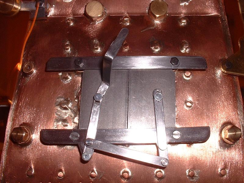
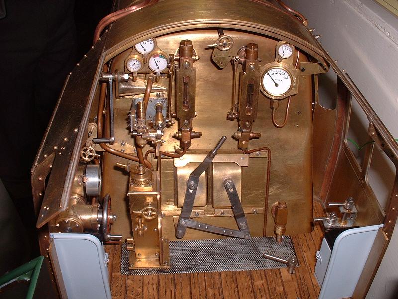
I've now completed the firebox doors. The photograph shows the improvements: correct lever geometry, a brass handle on the operating lever, a double thickness of steel plate on the doors, and the countersunk holes filled with solder and replaced by small-headed bolts. The linkage works very smoothly and the doors move symmetrically after repositioning the right-hand end of the connecting link 7mm below the pivot. Ideally there should something behind the runners to support the doors rather than relying just on the firehole edging, but if I make a cover for the backplate that will probably serve this purpose. This completes the first half of kit 18 - I'll continue with odd jobs on the tender while I wait for the final kit.
9/3/07
I've now completed the firebox doors. The photograph shows the improvements: correct lever geometry, a brass handle on the operating lever, a double thickness of steel plate on the doors, and the countersunk holes filled with solder and replaced by small-headed bolts. The linkage works very smoothly and the doors move symmetrically after repositioning the right-hand end of the connecting link 7mm below the pivot. Ideally there should something behind the runners to support the doors rather than relying just on the firehole edging, but if I make a cover for the backplate that will probably serve this purpose. This completes the first half of kit 18 - I'll continue with odd jobs on the tender while I wait for the final kit.
14/4/07 I've decided to paint the new tender drawbar and the bogie guard irons and some other parts at the same time as the buffer beam, since small painting sessions waste time and paint. The new drawbar is a better length - the slot allows the tender front buffers to touch the loco rear beam when pushed forward for display purposes, but hopefully gives sufficient leeway to go round corners when pulled back. The guard irons were rather low, touching the rails when the front of the bogie was pushed right down on its springs, so I bent them up slightly and also filed back the ends. The guard irons on 70013 are quite a way off the rails (although I guess they may be lower when the boiler is refitted).
16/12/07 Having now completed the cab and cladding in kit 18b, I've returned to this kit to complete the fitting of the running boards, starting with the left-hand board. I needed to cut about 5mm off the inner edge along the firebox cladding and about 2-3mm along the rear half of the barrel cladding to get a good fit - the running board now sits exactly horizontal and in line with the cab side. It doesn't quite rest on either of the intermediate brackets and I'll need to adjust or pack these up a little. The holes near the top of the smoke deflector line up with the 3 holes in the smokebox, but we have not yet had the brackets for these fixings and so I'll probably make some myself to avoid waiting. I'll also fit an angle strip to join the lower edge of the smoke deflector to the running board, as on the prototype. The front lower and sloping edges of the deflector are a couple of mm away from the front platework and I'll need to correct this in some way. I'll also sort out the edges of the side trim - see 5/2/07 above - and make proper dimpled steps for the front platework.
 18/12/07
I've more or less completed the left-hand running board. I decided to cut the front of the running board back so that it butts up behind the front plate, instead of overlapping it. I silver-soldered a tongue under the front of the running board and bolted the front plate over this. This gives a neater joint, and lowers the smoke deflector so that its lower front edge rests on the front plate. I then sorted out the front side trim - I cut off the lug halfway up the slope and soldered a piece in to fill the small gap, and then soft soldered the side trim to the front plate. I also soldered a sliver of steel into the gap along the top of the lower section and filed it all down to give a nice square edge. I found that the front running board bracket immediately behind the lubricator needs 3/16" of packing, and the rear bracket needs 1/8". I made the front packing from 3/16" steel with two M3 holes tapped into it and silver-soldered it to the underside of the running board, and then attached it to the bracket with two short bolts from underneath. They are slightly fiddly to get at, but the rear bracket should be easier. I'll fill the holes in the running board. This should look neater and will enable me to remove the running boards without disturbing the paintwork. I've noticed that the shaft for the reverser gear rubs hard against the underside of the rear bracket, and would clash with a nut or bolt in the outer hole, so I'll shorten the bracket and make a new hole further in.
18/12/07
I've more or less completed the left-hand running board. I decided to cut the front of the running board back so that it butts up behind the front plate, instead of overlapping it. I silver-soldered a tongue under the front of the running board and bolted the front plate over this. This gives a neater joint, and lowers the smoke deflector so that its lower front edge rests on the front plate. I then sorted out the front side trim - I cut off the lug halfway up the slope and soldered a piece in to fill the small gap, and then soft soldered the side trim to the front plate. I also soldered a sliver of steel into the gap along the top of the lower section and filed it all down to give a nice square edge. I found that the front running board bracket immediately behind the lubricator needs 3/16" of packing, and the rear bracket needs 1/8". I made the front packing from 3/16" steel with two M3 holes tapped into it and silver-soldered it to the underside of the running board, and then attached it to the bracket with two short bolts from underneath. They are slightly fiddly to get at, but the rear bracket should be easier. I'll fill the holes in the running board. This should look neater and will enable me to remove the running boards without disturbing the paintwork. I've noticed that the shaft for the reverser gear rubs hard against the underside of the rear bracket, and would clash with a nut or bolt in the outer hole, so I'll shorten the bracket and make a new hole further in.
 20/12/07
I've completed the left-hand running board, apart from filling some superfluous holes. I trimmed back the rear edges of the cutouts for the lubricator lid and handwheel to centralise them. The cover for the reverser shaft has rather unsightly flanges so I'll probably trim these off and solder the cover over the slot in the running board. I've started on the left-hand smoke deflector - I cut a groove using an engraving tool in the Dremel to simulate the joint at the lower front between the lines of rivet holes, and made a backing strip for this joint from thin steel which I rivetted in place. I've bent an
angle strip from 20 swg steel to fit on the outside of the smoke deflector to join it to the running board, replacing the brass angles supplied for the inside of the smoke deflector. This is fixed with 10 rivets in the smoke deflector and 5 10BA bolts in the running board.
20/12/07
I've completed the left-hand running board, apart from filling some superfluous holes. I trimmed back the rear edges of the cutouts for the lubricator lid and handwheel to centralise them. The cover for the reverser shaft has rather unsightly flanges so I'll probably trim these off and solder the cover over the slot in the running board. I've started on the left-hand smoke deflector - I cut a groove using an engraving tool in the Dremel to simulate the joint at the lower front between the lines of rivet holes, and made a backing strip for this joint from thin steel which I rivetted in place. I've bent an
angle strip from 20 swg steel to fit on the outside of the smoke deflector to join it to the running board, replacing the brass angles supplied for the inside of the smoke deflector. This is fixed with 10 rivets in the smoke deflector and 5 10BA bolts in the running board.
22/12/07 I made the three top brackets for the left-hand smoke deflector from 20 swg steel, each fixed to the smoke deflector with two 10BA bolts and to the smokebox with a small-headed 8BA bolt - the same head size as a 10BA standard head, and a good fit in the holes drilled in the smokebox. Bending the brackets to give the correct distance between smokebox and deflector involved some trial and error, but the final result has the smoke deflector exactly vertical and very rigid. I now just need to make the front steps, and then of course go through the whole process again for the right-hand side.
 23/12/07
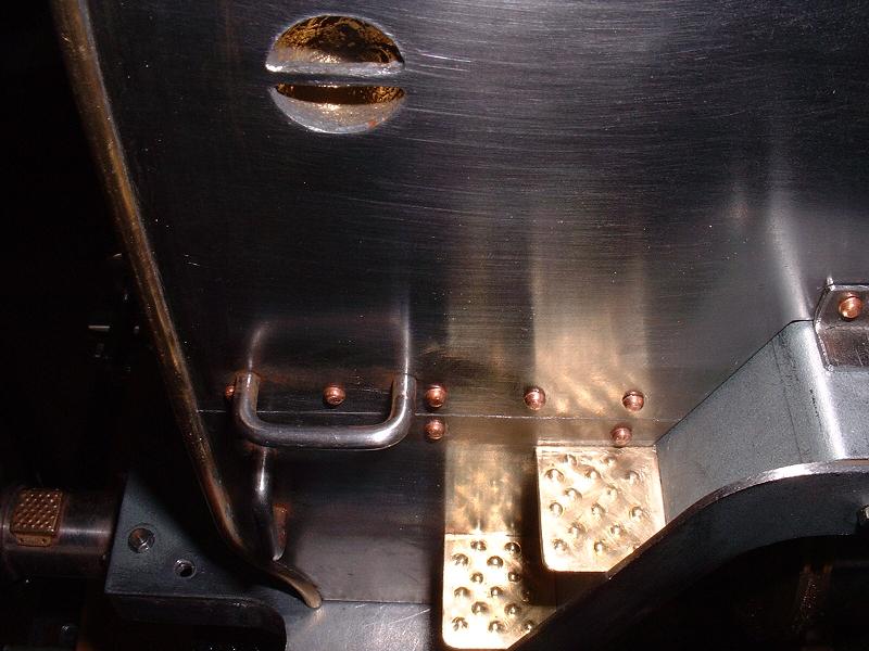
I've made and fitted the front steps, using the same dimpling technique as on the firebox steps. I thought that it would be tricky to solder the steps squarely to the front plate, so I cut a slot for each step in the relatively thick steel of the smoke deflector and soldered them into these. The photo shows a few traces of corrosion on the steel which are hardly visible to the naked eye, perhaps caused by not cleaning the flux off thoroughly enough after soldering.
23/12/07
I've made and fitted the front steps, using the same dimpling technique as on the firebox steps. I thought that it would be tricky to solder the steps squarely to the front plate, so I cut a slot for each step in the relatively thick steel of the smoke deflector and soldered them into these. The photo shows a few traces of corrosion on the steel which are hardly visible to the naked eye, perhaps caused by not cleaning the flux off thoroughly enough after soldering.
26/12/07 I've started fitting the right-hand running board, which needed trimming in much the same way as the left-hand one. One small error that Ted pointed out is that this running board has a semicircular cut-out in line with the boiler top feed so that the feed pipe from the injector can run under the board and emerge at the front to run up to the top feed, but on the prototype the feed pipes on both sides are fitted above the running boards. I'll solder in a piece of steel to fill this cut-out, and cut an opening just in front of the firebox to match the one on the left-hand side.
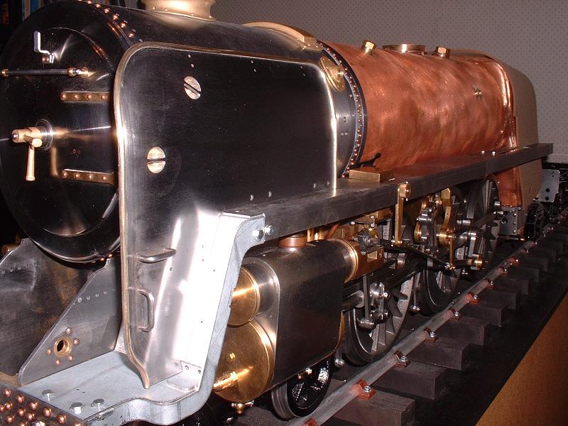
31/12/07 We had our last sail of 2007 yesterday - just a short hop from Lymington to Yarmouth on the Isle of Wight for lunch and a walk along the foreshore. I've completed the right-hand running board and front plate, and started on the smoke deflector. This is all taking a little longer because of the need to ensure that the measurements all match those of the left-hand side. The smoke deflector has a hole high up for the whistle bracket, but I'll fill this hole and fit the whistle to the side of the smokebox lower down where it should be less obvious - I might even fit it below the level of the running board. This working whistle obviously has to be far larger than scale and hidden away. No dummy replica whistle has been supplied, but I'll try to fabricate one, or buy a casting.
3/1/08 I've now completed the front platework, apart from filling superfluous holes. I'll tackle the spectacle plates next, which I'll describe under kit 18b. I see that Steamfittings who make some of the standard fittings for Modelworks now have water gauges in their online catalogue, so hopefully we'll be getting these soon.
| Next Kit | Previous Kit | Index |