15/5/07 I'm awaiting the second half of the final kit, which I think should contain the following parts:
25/5/07
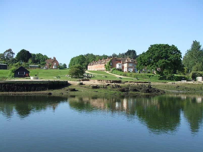
Just back from a few days sailing - the photo shows Buckler's Hard on the Beaulieu river, where Nelson's favourite ship Agamemnon was built. I phoned Debbie yesterday to check on progress on the final kit, and she said that the throatplate cladding castings have still not arrived. I gather from the forum on the 2" Burrell site that Dean has said that they have given up on getting castings made in India and have reverted to a UK supplier. Debbie did assure me that the Britannia would be the top priority once the castings arrive.4/6/07 Debbie tells me that the throatplate cladding castings have finally been delivered to Daventry, and she'll keep me informed of progress on the final kit.
17/8/07 Modelworks tell me that the boiler cladding is now complete and the firebox cladding is cut out and ready to be bent to shape, the cab platework is being punched, and most of the other parts are already in their boxes ready for despatch, including the pressure gauges. There has been a delay in supply of the injectors caused by illness at the suppliers, so another source may need to be found.
 28/8/07
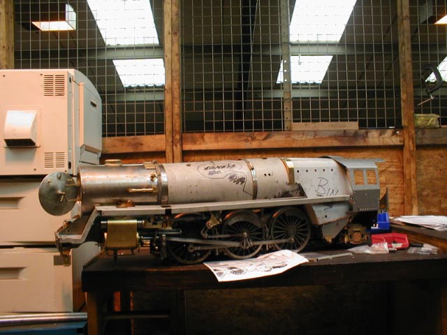
Ted visited Modelworks this morning and sent me this photo of the control model with the cladding and part of the cab fitted. He spoke to Dean who said he was hoping to ship the final kit later this week, although Ted thought after checking the contents of the boxes lined up for dispatch that next week might be more likely.
28/8/07
Ted visited Modelworks this morning and sent me this photo of the control model with the cladding and part of the cab fitted. He spoke to Dean who said he was hoping to ship the final kit later this week, although Ted thought after checking the contents of the boxes lined up for dispatch that next week might be more likely.
13/9/07 Kit 18b finally arrived at 10.30 this morning. The parts list appears at first glance to cover all of the items listed at the top of this page apart from the working tender draw bar and the shovel and poker. I've checked the parts against the parts list and confirmed that the dome cover casting, injectors, safety valves and water gauges are missing - Dean had forewarned me about these - along with the name and number plates, which he hadn't mentioned. I'm also missing one pipe, and have a duplicate of another - presumably a packing error on my particular kit. The replacement valve gear parts are not what I had asked Modelworks to produce - I'll write this up later under kit 13. I'll spend the next few days working through the parts list and instructions to see exactly what we've got. I must say that it's a relief finally to receive this kit, even though it's a year late compared with the original schedule - kit 16 was delivered in July 2006. Some word of explanation or apology from Modelworks would have been nice.
 14/9/07
The photograph shows the major cladding and cab components - I'll photograph other smaller parts as I unpack them, to avoid getting them mixed up. I've now read through all 57 steps of the instructions - they are summarised below (ignoring the items already covered in kit 18a, which are repeated in these instructions).
14/9/07
The photograph shows the major cladding and cab components - I'll photograph other smaller parts as I unpack them, to avoid getting them mixed up. I've now read through all 57 steps of the instructions - they are summarised below (ignoring the items already covered in kit 18a, which are repeated in these instructions).
15/9/07
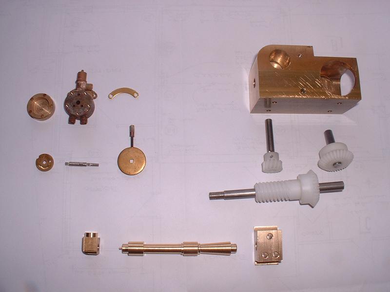
I decided to ease my way into this kit with trial assemblies of the steam brake valve, the reverser gearbox and the dummy vacuum ejector. This proved to be a dispiriting move, since there were problems with all three of them. The steam brake valve is a neat little device, but the squared ends of the spindle are much smaller than the square holes in the discs, and the spindle needs a thread and a very thin nut on the valve end to stop it pulling out. The nylon bevel gears for the reverser are too thick for the recess in the housing, and the spindle for the indicator wheel will not fit into its hole in the housing - it can be tapped half way in but will not turn. Also the 4-start worm gear will make the indicator wheel rotate several times between full forward and reverse - it really should only rotate less than one full turn, although this is a minor grumble and something I can live with. Finally, the ends of the dummy ejector central piece are distinctly larger than the holes in the end pieces. I'd be grateful if other builders could let me know if these faults are general, or specific to the machining of my kit.
 17/9/07
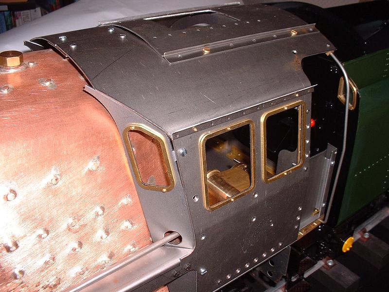
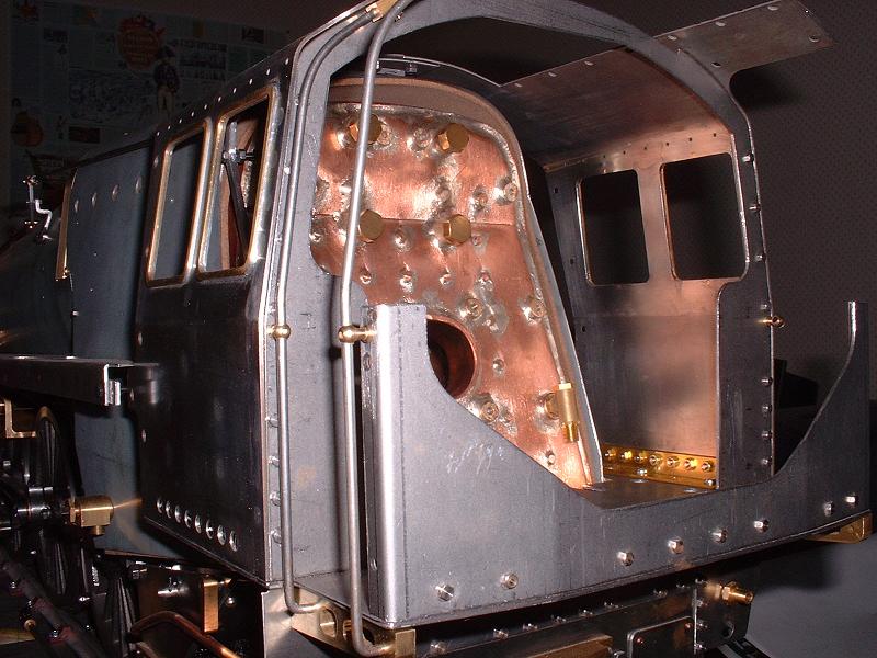
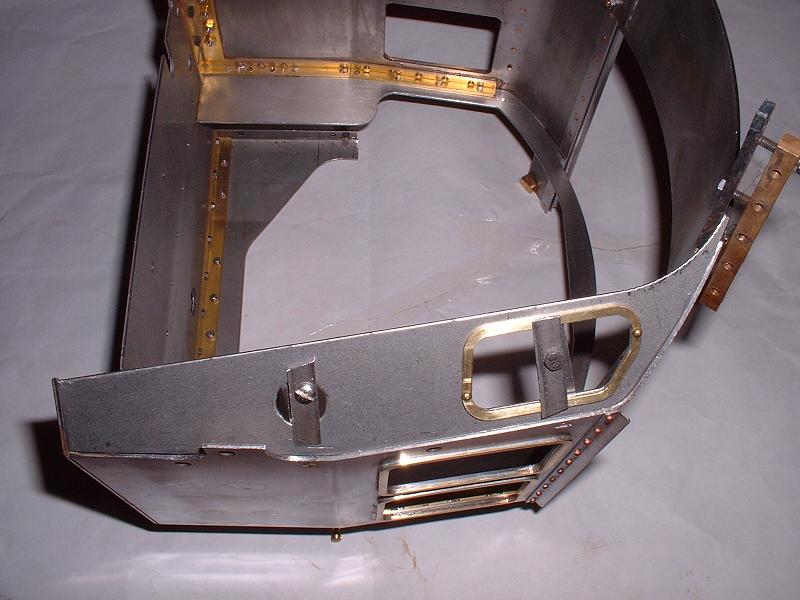
I've done a trial assembly of the cab, and I'm really quite pleased with the way it looks. It will just need a bit of filing and trimming, particularly around the spectacle plates and running boards to accommodate the firebox cladding. The roofline matches the tender almost exactly, and the running boards are very close to horizontal. As Jim in Australia, who's scratch-building a 5" model of 70036 'Boadicea' said in a recent email: 'In a dim light and with my eyes half-closed Boadicea is starting to take shape and with a bit of imagination I can almost hear her rapid exhaust beat as she races towards Ipswich and a 2 minute stop'! I can see what he means, although my eyes have to be rather more than half-closed to avoid seeing all the large countersunk screw holes in the cab sides, so I'll need to decide what to do about them. I said in kit 6 on 23/1/06 that I'd bolted the large rear buffer beam plate to the front face of the smaller plate, as on 70000 and an early photograph of 70013, but I've had to move it back to the rear face otherwise the cab which is attached to it sits too far forward. If it's any consolation, the current restoration of 70013 also has it moved to the rear face, but perhaps they will discover that their cab is too far back when they come to refit it. I could only fit one of the 4 handrails, because the other 3 had been made from thicker wire (1/8" rather than 3mm) and so didn't fit in their mounting holes. I'll need to get these replaced. Ian emailed to say that he had similar problems with his gearbox to those I described above, but he sorted them out with wet-and-dry sandpaper, so I put the indicator shaft in the electric drill and sanded it down to size, and also spun the bevel gears and removed some material from their back faces by paring with the back of a knife blade - the nylon 'machines' quite easily. I had to remove a fair amount, but the gearbox now works smoothly. I fitted it into the cab, screwing it to the cab side, but the reverser stand is about 9mm too low to support the gearbox and will need some packing pieces. The cardon shaft and gearbox output shaft are both too long to accommodate the universal joint inside the cab, but I'll pause for thought before taking a hacksaw to these.
17/9/07
I've done a trial assembly of the cab, and I'm really quite pleased with the way it looks. It will just need a bit of filing and trimming, particularly around the spectacle plates and running boards to accommodate the firebox cladding. The roofline matches the tender almost exactly, and the running boards are very close to horizontal. As Jim in Australia, who's scratch-building a 5" model of 70036 'Boadicea' said in a recent email: 'In a dim light and with my eyes half-closed Boadicea is starting to take shape and with a bit of imagination I can almost hear her rapid exhaust beat as she races towards Ipswich and a 2 minute stop'! I can see what he means, although my eyes have to be rather more than half-closed to avoid seeing all the large countersunk screw holes in the cab sides, so I'll need to decide what to do about them. I said in kit 6 on 23/1/06 that I'd bolted the large rear buffer beam plate to the front face of the smaller plate, as on 70000 and an early photograph of 70013, but I've had to move it back to the rear face otherwise the cab which is attached to it sits too far forward. If it's any consolation, the current restoration of 70013 also has it moved to the rear face, but perhaps they will discover that their cab is too far back when they come to refit it. I could only fit one of the 4 handrails, because the other 3 had been made from thicker wire (1/8" rather than 3mm) and so didn't fit in their mounting holes. I'll need to get these replaced. Ian emailed to say that he had similar problems with his gearbox to those I described above, but he sorted them out with wet-and-dry sandpaper, so I put the indicator shaft in the electric drill and sanded it down to size, and also spun the bevel gears and removed some material from their back faces by paring with the back of a knife blade - the nylon 'machines' quite easily. I had to remove a fair amount, but the gearbox now works smoothly. I fitted it into the cab, screwing it to the cab side, but the reverser stand is about 9mm too low to support the gearbox and will need some packing pieces. The cardon shaft and gearbox output shaft are both too long to accommodate the universal joint inside the cab, but I'll pause for thought before taking a hacksaw to these.
 18/9/07
I'm starting a trial assembly of the boiler and firebox lagging and cladding. The main cladding sections are made of zinc-plated steel rather than the brass shown in the brochure, but the upper throatplate cladding is a beautiful piece of solid brass weighing nearly 3lb. The saving from not using sheet brass cladding has probably been outweighed (literally) by the cost of this piece, which I've seen made from car body filler on scratch-built models! The steel will hold the paint better than brass and be less prone to dents, but I'm concerned that it might rust on the cut edges, particularly around the safety valves with the inevitable dampness in the lagging there. Ted has already assembled his cladding, and he tells me that it fits well apart from the holes for the regulator bracket on the side of the boiler barrel which are a bit too high.
18/9/07
I'm starting a trial assembly of the boiler and firebox lagging and cladding. The main cladding sections are made of zinc-plated steel rather than the brass shown in the brochure, but the upper throatplate cladding is a beautiful piece of solid brass weighing nearly 3lb. The saving from not using sheet brass cladding has probably been outweighed (literally) by the cost of this piece, which I've seen made from car body filler on scratch-built models! The steel will hold the paint better than brass and be less prone to dents, but I'm concerned that it might rust on the cut edges, particularly around the safety valves with the inevitable dampness in the lagging there. Ted has already assembled his cladding, and he tells me that it fits well apart from the holes for the regulator bracket on the side of the boiler barrel which are a bit too high.
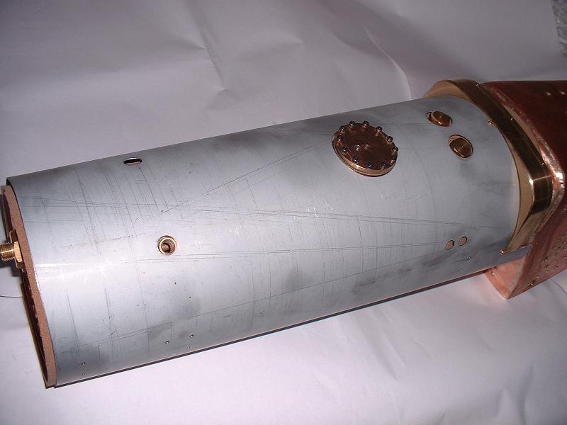
19/9/07 I've trimmed the barrel lagging to size - all the edges needed trimming and all the holes needed enlarging - and I've fitted the barrel cladding and the throatplate casting, as shown in this photograph. The lagging now just needs to be cut 10-11 mm back from the front of the barrel to allow the boiler to be inserted into the smokebox. I'll then fit the boiler bands to pull the cladding in tightly. I'll use small-headed M3 bolts in place of the pan head screws provided to attach the cladding to the throatplate casting. The cladding seems to be a very good fit, apart from the regulator bracket holes which are about 5mm too high. The whole top rear area of the cladding is intentionally about 10mm clear of the barrel and lagging, held out by the deep flange on the throatplate casting, so I think it should be possible to fabricate a small plate to be bolted to the bosses inside the cladding, with new bosses projecting through the holes to bolt the bracket to.
 20/9/07
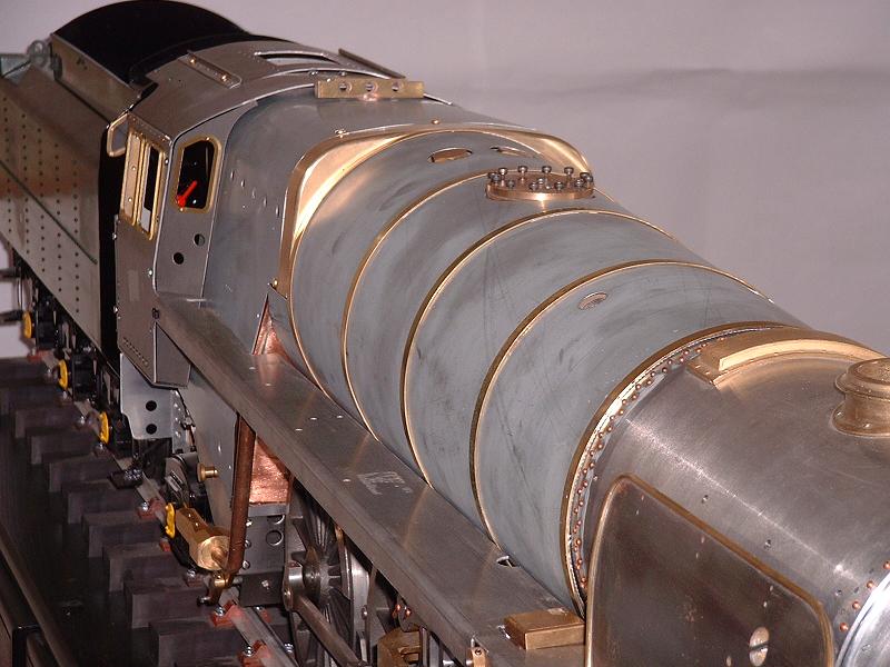
I've now fitted the boiler in its cladding to the smokebox, and trial-fitted the cab and running boards around it. The results look very encouraging, using Jim's eyes-half-closed test, and indeed pretty good even with eyes wide open. I trimmed the front of the barrel lagging to 11mm from the front of the boiler and fitted the throatplate casting and barrel cladding with its bands, and slid the front end into the smokebox and tightened the bands. The front end didn't close completely tightly around the smokebox - I think the two edges of the cladding must be touching underneath and will need trimming back a little. The cladding comes up to the lip on the smokebox at the top, but is angled away from it a little at the sides and underneath because of the upward slope of the barrel. However, the boiler band covers this gap. To get the boiler fully into the smokebox I had to remove the 6 bolts holding the front of the ashpan to the frames and rest the front edge of the foundation ring over these holes. I can easily replace these with countersunk screws later. I then fitted the firebox cladding to the throatplate casting. I didn't fit the firebox lagging at this stage since I haven't trimmed it to size, and I think it will need holes cutting round at least some of the firebox stay heads to get a close fit. Nor did I attempt to fit the lower throatplate cladding. With the firebox cladding screwed to the throatplate casting, the rear of the cladding was far too high and the hole for the turret was well above and in front of its boiler fitting. I rectified this by removing the 3 screws holding the barrel cladding to the throatplate casting, and rotating the throatplate and firebox cladding backwards away from the top of the barrel cladding. This fixed the alignment problem, and the rear boiler band covers the 4mm gap at the top of the cladding (although the top screw hole will need to be filled, and the band should really be a little further forward). I've assembled the cladding with the throatplate casting resting on top of the barrel lagging, as specified in the instructions, but I'm wondering whether the control model was done with the lagging cut away here, which would lower the top line and reduce this misalignment a bit. Anyway, the overall line of the barrel and firebox looks pretty authentic to me. I then fitted the cab and running boards. The reverser stand clashes with the firebox cladding and one or other will need to be trimmed a little, so I left this off, but apart from this it all fits nicely - I even managed to squeeze one of the spectacle plates in for the photograph, although this is cheating slightly since it pulls the cab over to one side. The running boards are quite a tight fit against the cladding and I think will benefit from filing back a little. All in all, a very satisfying morning's work.
20/9/07
I've now fitted the boiler in its cladding to the smokebox, and trial-fitted the cab and running boards around it. The results look very encouraging, using Jim's eyes-half-closed test, and indeed pretty good even with eyes wide open. I trimmed the front of the barrel lagging to 11mm from the front of the boiler and fitted the throatplate casting and barrel cladding with its bands, and slid the front end into the smokebox and tightened the bands. The front end didn't close completely tightly around the smokebox - I think the two edges of the cladding must be touching underneath and will need trimming back a little. The cladding comes up to the lip on the smokebox at the top, but is angled away from it a little at the sides and underneath because of the upward slope of the barrel. However, the boiler band covers this gap. To get the boiler fully into the smokebox I had to remove the 6 bolts holding the front of the ashpan to the frames and rest the front edge of the foundation ring over these holes. I can easily replace these with countersunk screws later. I then fitted the firebox cladding to the throatplate casting. I didn't fit the firebox lagging at this stage since I haven't trimmed it to size, and I think it will need holes cutting round at least some of the firebox stay heads to get a close fit. Nor did I attempt to fit the lower throatplate cladding. With the firebox cladding screwed to the throatplate casting, the rear of the cladding was far too high and the hole for the turret was well above and in front of its boiler fitting. I rectified this by removing the 3 screws holding the barrel cladding to the throatplate casting, and rotating the throatplate and firebox cladding backwards away from the top of the barrel cladding. This fixed the alignment problem, and the rear boiler band covers the 4mm gap at the top of the cladding (although the top screw hole will need to be filled, and the band should really be a little further forward). I've assembled the cladding with the throatplate casting resting on top of the barrel lagging, as specified in the instructions, but I'm wondering whether the control model was done with the lagging cut away here, which would lower the top line and reduce this misalignment a bit. Anyway, the overall line of the barrel and firebox looks pretty authentic to me. I then fitted the cab and running boards. The reverser stand clashes with the firebox cladding and one or other will need to be trimmed a little, so I left this off, but apart from this it all fits nicely - I even managed to squeeze one of the spectacle plates in for the photograph, although this is cheating slightly since it pulls the cab over to one side. The running boards are quite a tight fit against the cladding and I think will benefit from filing back a little. All in all, a very satisfying morning's work.
 21/9/07
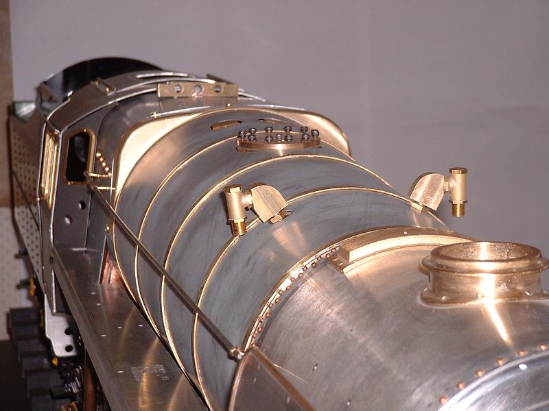
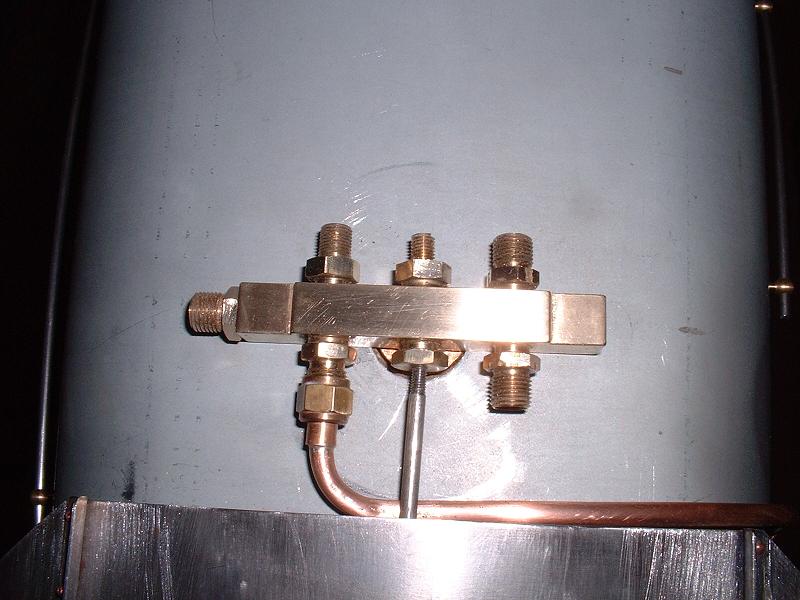
I've checked out some of the fittings on the boiler and firebox. The handrails are each supported by 6 stanchions - one on the smokebox, 3 on the barrel and 2 on the firebox. The smokebox and firebox holes have been drilled and tapped 6BA, but the holes in the barrel cladding have been left for the customer to drill, which I think is a sensible move since it will allow them to be lined up correctly (although the instructions say that it is the firebox rather than the barrel holes that need to be drilled). The handrails fit nicely through the 3 stanchions - I won't drill the barrel holes until the cladding alignment is finalised. It would have been better if the smokebox stanchions had been fitted through clearance holes with a nut on the inside, to allow the boiler to be removed in the future without disturbing the paint on the handrails, but unfortunately the stanchion threads are not long enough to go right through the very thick smokebox wall. However, clearance holes and nuts on the barrel cladding should be fine, so it won't be necessary to buy a 6BA tap. The dummy washout plugs fit into the holes on each side of the firebox cladding. One of the plugs on my firebox clashes with a protruding firebox stay, so I'll have to cut the plug to fit over it as best I can. There are 5 holes on each side, but 12 plugs supplied - in fact there should be 11 plugs, 6 on the left and 5 on the right. There isn't space at the rear of the left hand side to drill the 6th hole, so I'll have to live with this slight inaccuracy - the annoying thing is that I know that Modelworks were told about this before the cladding was produced. The two top feed clack valves fit into their boiler bushes via adaptors and angled blocks, but on mine the right hand valve is well off the vertical, as shown in this photograph - the bush in the boiler must be out of line. This really needs fixing, because apart from the cosmetic effect the input to the clack valve is too close to the cladding to take the feed pipe. The angled blocks will benefit from substantial rounding off of the square edges.
21/9/07
I've checked out some of the fittings on the boiler and firebox. The handrails are each supported by 6 stanchions - one on the smokebox, 3 on the barrel and 2 on the firebox. The smokebox and firebox holes have been drilled and tapped 6BA, but the holes in the barrel cladding have been left for the customer to drill, which I think is a sensible move since it will allow them to be lined up correctly (although the instructions say that it is the firebox rather than the barrel holes that need to be drilled). The handrails fit nicely through the 3 stanchions - I won't drill the barrel holes until the cladding alignment is finalised. It would have been better if the smokebox stanchions had been fitted through clearance holes with a nut on the inside, to allow the boiler to be removed in the future without disturbing the paint on the handrails, but unfortunately the stanchion threads are not long enough to go right through the very thick smokebox wall. However, clearance holes and nuts on the barrel cladding should be fine, so it won't be necessary to buy a 6BA tap. The dummy washout plugs fit into the holes on each side of the firebox cladding. One of the plugs on my firebox clashes with a protruding firebox stay, so I'll have to cut the plug to fit over it as best I can. There are 5 holes on each side, but 12 plugs supplied - in fact there should be 11 plugs, 6 on the left and 5 on the right. There isn't space at the rear of the left hand side to drill the 6th hole, so I'll have to live with this slight inaccuracy - the annoying thing is that I know that Modelworks were told about this before the cladding was produced. The two top feed clack valves fit into their boiler bushes via adaptors and angled blocks, but on mine the right hand valve is well off the vertical, as shown in this photograph - the bush in the boiler must be out of line. This really needs fixing, because apart from the cosmetic effect the input to the clack valve is too close to the cladding to take the feed pipe. The angled blocks will benefit from substantial rounding off of the square edges.
 24/9/07
I'll remove the cab and boiler again in order to adjust the barrel cladding, fit the firebox lagging and lower throatplate cladding and try fitting the steam pipes into the boiler and smokebox. No instructions have been given for fitting the steam pipes to the boiler, and I've asked Debbie to provide some, but the assembly seems fairly clear. The photograph shows the parts, most of which were included in kit 18a - the steam collection pipe from kit 18b is screwed into the back of the regulator adaptor and the adaptor is screwed into the bush on the front of the boiler, with the rear end of the steam collection pipe supported by the bracket on the underside of the dome cover. The regulator valve and banjo bolt are then fitted to the front of the adaptor, and the superheater assembly from kit 17 is fitted over the banjo bolt and held with the two aluminium washers and brass nut. The boiler is then fitted to the smokebox and the superheater outlet pipes will hopefully line up with the steam pipes in the sides of the smokebox. The snifter pipes then need to be connected from the bosses on the superheater pipes to the snifter valve in the side of the smokebox, but they haven't been supplied yet. The regulator valve is connected to the regulator spindle and smokebox bush supplied in kit 14, but I'm pretty sure that there is a part missing here to fit over the flats on the valve and spindle. The steam collection pipe is open at the rear end, and I had expected some sort of upward pointing end piece to collect the steam from the highest point under the dome. However, I've made some enquiries and it seems that some scratch-built Britannia boilers don't have dome openings at all and the steam collection pipe is supported by a bracket between the safety valves, so perhaps the pipe supplied will be OK as it is. If water gets carried over when steaming I can always modify it later.
24/9/07
I'll remove the cab and boiler again in order to adjust the barrel cladding, fit the firebox lagging and lower throatplate cladding and try fitting the steam pipes into the boiler and smokebox. No instructions have been given for fitting the steam pipes to the boiler, and I've asked Debbie to provide some, but the assembly seems fairly clear. The photograph shows the parts, most of which were included in kit 18a - the steam collection pipe from kit 18b is screwed into the back of the regulator adaptor and the adaptor is screwed into the bush on the front of the boiler, with the rear end of the steam collection pipe supported by the bracket on the underside of the dome cover. The regulator valve and banjo bolt are then fitted to the front of the adaptor, and the superheater assembly from kit 17 is fitted over the banjo bolt and held with the two aluminium washers and brass nut. The boiler is then fitted to the smokebox and the superheater outlet pipes will hopefully line up with the steam pipes in the sides of the smokebox. The snifter pipes then need to be connected from the bosses on the superheater pipes to the snifter valve in the side of the smokebox, but they haven't been supplied yet. The regulator valve is connected to the regulator spindle and smokebox bush supplied in kit 14, but I'm pretty sure that there is a part missing here to fit over the flats on the valve and spindle. The steam collection pipe is open at the rear end, and I had expected some sort of upward pointing end piece to collect the steam from the highest point under the dome. However, I've made some enquiries and it seems that some scratch-built Britannia boilers don't have dome openings at all and the steam collection pipe is supported by a bracket between the safety valves, so perhaps the pipe supplied will be OK as it is. If water gets carried over when steaming I can always modify it later.
 25/9/07
I've now managed to fit the boiler with its steam pipes into the smokebox, although it was quite a struggle. In order to get the outlet pipes far enough forward to align with the cylinder pipes I had to pull the boiler as far forward as it would go and also put 3 aluminium washers behind the banjo fitting - 2 extra washers had been provided in kit 18b. I had to bend one of the pipes a bit - the right-hand one in this picture - and it still doesn't fit very squarely onto the threaded pipe, so may not be steamtight and will probably need some more serious bending. I had to loosen and raise the smokebox temporarily in order to get the pipes over the ends of the threaded pipes. The worst problem is that the spindle of the regulator valve is about 10mm higher than the spindle in the side of the smokebox, so I had to tilt the regulator valve down to point towards it as shown in the top right of the photograph. It will need a connecting piece with a fair amount of angular freedom to connect the two, and I'm doubtful as to how well this linkage is going to work. I've also drilled out the two end pieces of the dummy ejector to 6mm to fit the central piece (see 15/9/07 above), and removed this item from the list below. I've arranged to visit Daventry on Thursday to get my boiler feed bush realigned and discuss the outstanding issues below.
25/9/07
I've now managed to fit the boiler with its steam pipes into the smokebox, although it was quite a struggle. In order to get the outlet pipes far enough forward to align with the cylinder pipes I had to pull the boiler as far forward as it would go and also put 3 aluminium washers behind the banjo fitting - 2 extra washers had been provided in kit 18b. I had to bend one of the pipes a bit - the right-hand one in this picture - and it still doesn't fit very squarely onto the threaded pipe, so may not be steamtight and will probably need some more serious bending. I had to loosen and raise the smokebox temporarily in order to get the pipes over the ends of the threaded pipes. The worst problem is that the spindle of the regulator valve is about 10mm higher than the spindle in the side of the smokebox, so I had to tilt the regulator valve down to point towards it as shown in the top right of the photograph. It will need a connecting piece with a fair amount of angular freedom to connect the two, and I'm doubtful as to how well this linkage is going to work. I've also drilled out the two end pieces of the dummy ejector to 6mm to fit the central piece (see 15/9/07 above), and removed this item from the list below. I've arranged to visit Daventry on Thursday to get my boiler feed bush realigned and discuss the outstanding issues below.
26/9/07 I've done a trial fitting of the lower throatplate cladding. Contrary to what the instructions say, this needs to be bolted to the front of the firebox cladding before sliding them both on from the front of the boiler barrel, otherwise the nuts and bolts cannot be fitted - alternatively, the nuts could be soldered to the back of the flanges. I had to file the top ends of the inner curve to fit around the barrel lagging. The throatplate cladding seems slightly too narrow at the top - it is pulling the firebox cladding sides in too much at that point. I'll try to flatten out the upper flanges and remake them so that the flanges are smaller and the front is wider. The barrel cladding is then fitted in front of the throatplate cladding, although the latter needs to be moved back a little, more nearly flush with the front of the firebox cladding, to enable the barrel cladding to go fully back.
27/9/07 I visited Daventry this morning and got my boiler top feed bush realigned - the boilermaker screwed in a threaded rod and levered it into line, the surrounding copper being quite malleable. Unfortunately Debbie was unwell and had gone home by the time I arrived so I couldn't discuss the generic items below. I have emailed the list to her and to Arthur the designer. I was able to exchange a few faulty items, including the thicker cab rails mentioned on 17/9/07 above - at least half the stock is affected, so most builders are likely to find some of their four rails too thick. The whistle pipe is missing from all kits so I've added it to the list below. I noticed that on the control model the regulator bracket bushes do line up with their cladding holes, but apparently the cladding was changed prior to the production run so this may explain the discrepancy. I saw at least 20 boxes of kit 18b lined up in dispatch in various stages of packing - 24 have been shipped so far.
28/9/07 I've slightly widened the upper sides of the lower throatplate cladding by flattening out the flanges and bending them again, but this proved quite tricky and I'm not sure that the effort was really worthwhile. I've fitted the firebox lagging, cutting it to fit around the stay ends on the top and the upper sides so that it lies flat. I bolted the firebox and lower throatplate cladding together using small-headed M3 bolts, which look much better than panhead screws, and the assembly can just be slid over the lagging, although it's quite a tight fit and I may try to reduce the lagging further around the front top and upper sides. I'll try to make a plate to carry the regulator bracket before refitting the barrel cladding. I shall definitely try to make a sheet of brass cladding for the boiler backplate - it should improve the appearance considerably, and hide the ends of the firebox lagging.
 30/9/07
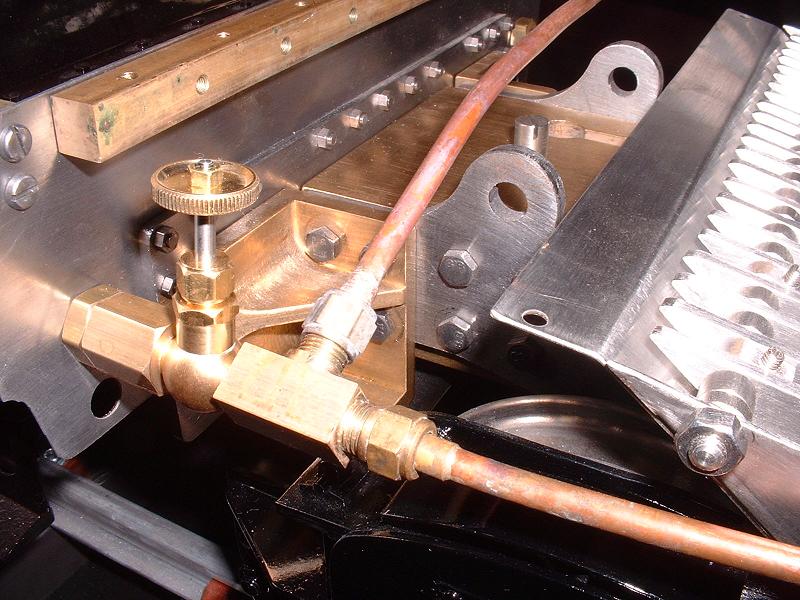
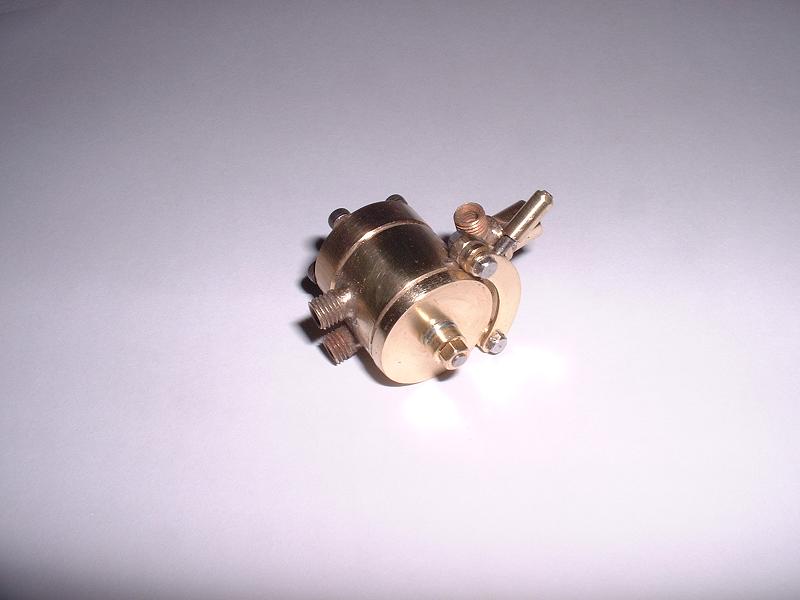
As a change from wrestling with the cladding, I've started to check out the pipework. I didn't fit the axle pump pipes in kit 9 - Ted said at the time that I would regret this, and he's right. The inlet pipe from the rear beam to the bottom pump connector looks easy enough, but the nut on the output pipe from the top of the pump will not fit through the small gap between the top of the axle pump stretcher and the main stretcher between the tops of the frames. I knew this all along, but had put off sorting it out. I'll now need to dismantle quite a lot to do so. I assembled the bypass valve for the other end of the pump output pipe, as shown in the photograph. This fits on the right hand side of the rear beam, using one of the three straight-through valves - when this valve is closed, the water is directed to the left-hand clack valve on the boiler backhead, and when it is open the water flows back through the overflow pipe to the tender. There's an extension for the valve spindle to allow the handwheel to project through the cab floor. I then started to assemble the injector water feed pipes on the left hand side of the rear beam, but soon discovered that part SP53400, a tee piece, is missing from the parts list and the kit, so I've emailed Debbie about this and added it to the list below. I saw that Debbie had used two of the right-angled valves for the injector water feeds on the control model, but I think this may cause the pipes to clash with the rear pony truck when she comes to fit the injectors. The ISO drawings show straight-through valves, so I've left this item in the list below for the time being.
30/9/07
As a change from wrestling with the cladding, I've started to check out the pipework. I didn't fit the axle pump pipes in kit 9 - Ted said at the time that I would regret this, and he's right. The inlet pipe from the rear beam to the bottom pump connector looks easy enough, but the nut on the output pipe from the top of the pump will not fit through the small gap between the top of the axle pump stretcher and the main stretcher between the tops of the frames. I knew this all along, but had put off sorting it out. I'll now need to dismantle quite a lot to do so. I assembled the bypass valve for the other end of the pump output pipe, as shown in the photograph. This fits on the right hand side of the rear beam, using one of the three straight-through valves - when this valve is closed, the water is directed to the left-hand clack valve on the boiler backhead, and when it is open the water flows back through the overflow pipe to the tender. There's an extension for the valve spindle to allow the handwheel to project through the cab floor. I then started to assemble the injector water feed pipes on the left hand side of the rear beam, but soon discovered that part SP53400, a tee piece, is missing from the parts list and the kit, so I've emailed Debbie about this and added it to the list below. I saw that Debbie had used two of the right-angled valves for the injector water feeds on the control model, but I think this may cause the pipes to clash with the rear pony truck when she comes to fit the injectors. The ISO drawings show straight-through valves, so I've left this item in the list below for the time being.
 1/10/07
I've now fitted the axle pump pipes. I removed the weighshaft brackets and unbolted the pump stretcher and slid it down about 10mm, which enabled me to slide the output pipe through the gap under the main stretcher without having to cut into the stretchers. Bending the pipes to shape and wiggling them into position was still quite tricky. The photograph shows how I arranged them - the input pipe on the left is bent up slightly to clear the pony and then runs down across the side of the ashpan and under the frames, under the trailing horn stays and over the middle horn stays to one side of the pump eccentric and then in towards the centre to reach the pump. The output pipe runs under the main stretcher on the right hand side, then curves up and over the rear of the frames in front of the firebox, and back horizontally along the side of the firebox before dipping down slightly to connect to the bypass valve. The fitting on the rear beam for the inlet pipe has a threaded end to take a pressurised pipe from the handpump, but I plan to get an extra set of pipes and feed the handpump directly to the other boiler clack valve. The flexible hoses supplied are far too stiff to bend down in the short gap between the loco and tender - the non-pressurised pipes could use much thinner and more flexible tubing, but I think a right-angled bend on the pressurised fitting will be needed to enable that pipe to run down under the tender beam.
1/10/07
I've now fitted the axle pump pipes. I removed the weighshaft brackets and unbolted the pump stretcher and slid it down about 10mm, which enabled me to slide the output pipe through the gap under the main stretcher without having to cut into the stretchers. Bending the pipes to shape and wiggling them into position was still quite tricky. The photograph shows how I arranged them - the input pipe on the left is bent up slightly to clear the pony and then runs down across the side of the ashpan and under the frames, under the trailing horn stays and over the middle horn stays to one side of the pump eccentric and then in towards the centre to reach the pump. The output pipe runs under the main stretcher on the right hand side, then curves up and over the rear of the frames in front of the firebox, and back horizontally along the side of the firebox before dipping down slightly to connect to the bypass valve. The fitting on the rear beam for the inlet pipe has a threaded end to take a pressurised pipe from the handpump, but I plan to get an extra set of pipes and feed the handpump directly to the other boiler clack valve. The flexible hoses supplied are far too stiff to bend down in the short gap between the loco and tender - the non-pressurised pipes could use much thinner and more flexible tubing, but I think a right-angled bend on the pressurised fitting will be needed to enable that pipe to run down under the tender beam.
 3/10/07
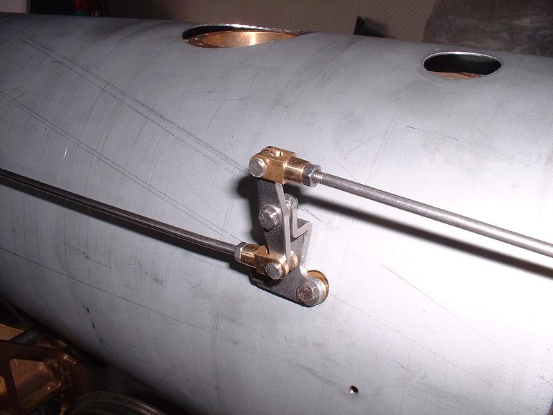
I've done a trial assembly of the regulator linkage. To correct the misalignment between the boiler bushes for the middle bracket and the corresponding holes in the cladding, I made a plate about 1" square from 1/4" brass bar with countersunk holes to bolt it to the boiler bushes, and holes tapped M3 about 6mm higher up to carry the bracket. The cladding slides over this with room to spare. There are two spacers provided (OC51274) which I think are intended to fit under the bracket, but with this modification they are unnecessarily thick so I made some new ones about 3.5mm thick. This arrangement works well and perhaps Modelworks will make a similar plate for other builders - I've left the issue in the list below. I had to bend the middle bracket to get the pivot pin horizontal. When the regulator lever pivot pin is fully screwed into its bracket on the back of the firebox, the top of the lever and its clevis foul the firebox cladding. I think this is because the rear end of the firebox cladding is well clear of the lagging and firebox, particularly towards the top. I've left the pin only half screwed in for the moment, but I'll probably make a better bracket at some stage. Apart from this, the linkage works nicely with no free play - it will be interesting to see how it copes with the rather stiff regulator valve when we get the connecting piece.
3/10/07
I've done a trial assembly of the regulator linkage. To correct the misalignment between the boiler bushes for the middle bracket and the corresponding holes in the cladding, I made a plate about 1" square from 1/4" brass bar with countersunk holes to bolt it to the boiler bushes, and holes tapped M3 about 6mm higher up to carry the bracket. The cladding slides over this with room to spare. There are two spacers provided (OC51274) which I think are intended to fit under the bracket, but with this modification they are unnecessarily thick so I made some new ones about 3.5mm thick. This arrangement works well and perhaps Modelworks will make a similar plate for other builders - I've left the issue in the list below. I had to bend the middle bracket to get the pivot pin horizontal. When the regulator lever pivot pin is fully screwed into its bracket on the back of the firebox, the top of the lever and its clevis foul the firebox cladding. I think this is because the rear end of the firebox cladding is well clear of the lagging and firebox, particularly towards the top. I've left the pin only half screwed in for the moment, but I'll probably make a better bracket at some stage. Apart from this, the linkage works nicely with no free play - it will be interesting to see how it copes with the rather stiff regulator valve when we get the connecting piece.
4/10/07 I mentioned the need for straight-through injector water feed valves on 30/9 above, but on checking the straight-through globe valves supplied for the steam feeds I noticed that they have much more constricted internal passageways, which is probably inevitable given the way they have to be drilled at an angle to reach above and below the valve seat. I'm sure that this is fine for high-pressure steam, but perhaps not so good for the water feeds where a high volume of water has to be sucked through on a much lower pressure difference. I've raised this question with Dean at Steamfittings, but I think I'll probably stick with the 90 degree valves supplied and change the pipework and T-piece to mount the valves further inboard and higher up under the cab floor, which will give room to bend the output pipes clear of the pony truck and will also make the valve handwheels much easier to get at when driving. We will still need to swap the remaining two 90 degree valves with small side connectors for one straight-through valve for the blower.
 7/10/07
I've now sorted out the steam brake valve (see 15/9/07 above) by making a new spindle from a length of 3mm steel rod. I carefully drilled and tapped this 8BA at each end and then filed each end down square to fit the valve disk and the operating lever. I opened out the square holes in these slightly with a square needle file to avoid the flats on the spindle breaking through to the threaded holes. I then assembled it with a thin-headed 8BA bolt holding the valve disk down, and an 8BA steel stud at the other end carrying one of the spring washers supplied, followed by a brass collar fashioned from an M3 nut, and an 8BA nut to hold it all in place. With a smearing of steam oil to lubricate the valve disk and the spring washer tightened down until it was fairly flat, the valve seems to operate very nicely, at least when blowing into the inlet pipe. When the valve is closed the outlet pipe to the brake cylinder connects to the exhaust pipe via the channel milled in the valve disk, to release the brake pressure. It will be interesting to see how effective the steam brakes turn out to be - I expect that the brakes on the driving trolley will be more use in practice.
7/10/07
I've now sorted out the steam brake valve (see 15/9/07 above) by making a new spindle from a length of 3mm steel rod. I carefully drilled and tapped this 8BA at each end and then filed each end down square to fit the valve disk and the operating lever. I opened out the square holes in these slightly with a square needle file to avoid the flats on the spindle breaking through to the threaded holes. I then assembled it with a thin-headed 8BA bolt holding the valve disk down, and an 8BA steel stud at the other end carrying one of the spring washers supplied, followed by a brass collar fashioned from an M3 nut, and an 8BA nut to hold it all in place. With a smearing of steam oil to lubricate the valve disk and the spring washer tightened down until it was fairly flat, the valve seems to operate very nicely, at least when blowing into the inlet pipe. When the valve is closed the outlet pipe to the brake cylinder connects to the exhaust pipe via the channel milled in the valve disk, to release the brake pressure. It will be interesting to see how effective the steam brakes turn out to be - I expect that the brakes on the driving trolley will be more use in practice.
8/10/07 My next task is to decide how to finish the cab platework. Although the general shape and appearance is pretty good, there are some details that could be improved:
 cab seats and reverser mounting, noting that there are more rivets on the driver's side than the fireman's. I shall probably cut the tops of the sides back to the correct position for the upper rain strips and make new fixed and sliding roof sections, with the joints hidden by the rain strips, and fit correct scale roof hatches on the sliding section. I'll use small-headed M3 bolts on the floor and bulkhead edge connections so that the cab could be dismantled if necessary, although it will normally be removed from the frames as a single unit. Apologies if this is getting a bit long-winded, but I like to get my thoughts down in writing before wielding the hacksaw!
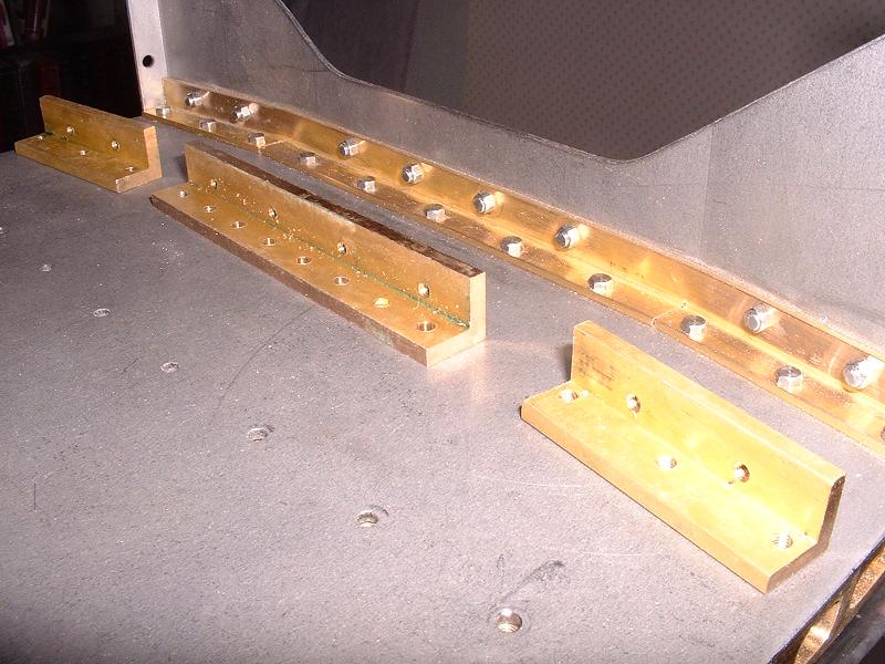
10/10/07 I've bought some 1/16" brass angle in 1/4" and 3/8" widths and started to assemble the cab. The photograph shows the rear guard secured with a continuous length of 3/8" angle and small-headed M3 bolts, with the three thicker angles as supplied in the foreground for comparison. The smaller continuous section looks much neater, and quite similar to the real thing as shown here. I had to notch the inner sides of the floor support brackets to accommodate the outermost bolts. I'll use 1/4" angle to fix the cab sides to the bulkhead, but I'll have to retain the thick section angles between the cab sides and floor because the reverser support is brazed to one of them.
13/10/07
Just back from a couple of days sailing - back to Buckler's Hard as pictured 5 months ago at the top of this page. I've fitted the 1/4" X 1/16" angle to one of the cab sides. I made a 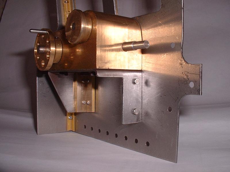 jig from a strip of steel with a countersunk threaded hole to speed up the process of filing down the countersunk screw heads so that they sit slightly below the level of the platework, and I'll fill them with solder later. I couldn't increase the size of the countersinks, which would have been quicker, because they would have encroached into the brass angle.
15/10/07 I wanted to avoid fixing the gearbox permanently to the cab side with countersunk screws that could not be removed once filled and painted, so I decided to adapt the supporting bracket and fix it rigidly to the cab side, then fix the gearbox just to the bracket and not directly to the cab. I cut the bracket just above the points where it is brazed to the angle along the bottom of the cab side, and fixed it to the cab side using the two short pieces of 1/2" x 1/8" brass angle that I had spare after my changes to the rear guard mounting. I also trimmed some material from the front leg of the bracket so that it clears the firebox cladding. This modification avoids the need to make spacers to compensate for the fact that the bracket was some 9mm lower than the bottom of the gearbox. Having separated the bracket from the angle, I've decided to get some 1/2" x 1/16" angle to fix the cab sides to the floor.
 17/10/07
I've fitted the window frames to the cab sides, fixing them first with the brass rivets supplied and then running solder all the way round and filing the rivets down flush. I also filled the countersunk screw heads with solder. I used Carr's Green Label flux, which works well on the steel plate. The photograph shows the front window frame and lower screws more or less cleaned up, and the rear frame and upper screws as soldered.
17/10/07
I've fitted the window frames to the cab sides, fixing them first with the brass rivets supplied and then running solder all the way round and filing the rivets down flush. I also filled the countersunk screw heads with solder. I used Carr's Green Label flux, which works well on the steel plate. The photograph shows the front window frame and lower screws more or less cleaned up, and the rear frame and upper screws as soldered.
20/10/07 I've now soldered and filed all the window frames and most of the countersunk screws. At some later stage when I'm sure that no more filing is needed, I'll fit rivets in the correct positions. These photos that I took of 70013's cab at Loughborough show the different patterns on the left and right sides. For some reason 70013 doesn't seem to have the vertical row of rivets down the front of the left-hand (driver's) seat, as seen on the right side and on other Britannias. Some of the rivet positions clash with the countersunk screws, but I hope that the soldered filling will allow me to drill them nevertheless. I'll need to glue them in place to avoid disturbing the solder.
22/10/07 I've been trying to make some new full-length rain strips to fit on the cab roof in the correct position a little below the edges of the current sliding section, but it's proving difficult to make a long sharp fold on the edge of a sheet of 20 swg steel without the proper equipment. I'll try to find a piece of scrap steel with existing angled edges, such as an old baking tray or PC chassis, and cut the roof strips from this.
26/10/07 I noticed that Chronos do an 18" mini bending brake for bending sheet metal up to 1.6mm thick, and relatively cheap at Ł24.96, so I went along today and bought one - it will doubtless come in handy for other jobs in the future. It makes a clean right-angled bend on the 20 swg steel that I bought to make the longer rain strips, almost as sharp as the angle on the strips supplied by Modelworks. I now just need to bend a sheet of 16 swg steel to the correct radius for the cab roof, and then I'll be ready to take the plunge and cut the tops of the cab sides back to the line of the upper rain strips and fit the fixed and removable sections of my new cab roof.
29/10/07 I've fixed the cab sides to the floor with full-length strips of 1/2" X 1/16" brass angle, which look a lot neater than the 1/8" angle supplied, and I've tried fitting the cab handrails. The front ones fit reasonably well after slight adjustment of their bends, although the top mounting blocks do not lie quite flat under the cab roof and I shall probably make some new ones with M3 rather than 6BA holes for countersunk screws. The rear handrails don't fit so well - the rear holes in the cab roof are too far back, with a gap of 50mm between the holes in the roof for the tops of the handrails compared with 46mm between the holes in the floor support brackets for the bottom ends. Also the holes for the stanchions in the rear guard plate have been drilled 3mm rather than tapped 6BA, and are higher than the front stanchions, so I'll drill and tap new holes for these.
 1/11/07
I've fitted collars to the stanchions, which I made from 6BA brass nuts by spinning them in the electric drill and shaping them with a grinding wheel in the Dremel - it's surprising what you can achieve without a lathe. This allowed me to fix the rear stanchions with nuts through new plain holes in the rear guard, as on 70000, at the same height as the stanchions on the front handrails. I've adapted the top handrail mounting blocks by filing them at an angle so that they lie flat under the roof, and fixed them with 6BA countersunk screws so that I'll be able to cover the screw heads with solder. I've drilled the front blocks and fixed them with nuts so that I can remove the blocks and handrails if necessary - on the rear ones the stanchions can be unbolted to free the rails. I've made new holes for the rear handrail top mounts, and I'll also trim the rear end of the cab roof which extends back further than it should - it should end in line with the outer rear edge of the cab floor. The proportions of the cab sides also seem slightly wrong - the stanchions and the top of the rear guard should be above the bottom of the cab windows, not below. I think the windows should extend further down and the rear guard should be a bit higher, but there's not much that I can do about this (short of buying Doug Hewson's cab kit, which looks very nice but is rather expensive).
1/11/07
I've fitted collars to the stanchions, which I made from 6BA brass nuts by spinning them in the electric drill and shaping them with a grinding wheel in the Dremel - it's surprising what you can achieve without a lathe. This allowed me to fix the rear stanchions with nuts through new plain holes in the rear guard, as on 70000, at the same height as the stanchions on the front handrails. I've adapted the top handrail mounting blocks by filing them at an angle so that they lie flat under the roof, and fixed them with 6BA countersunk screws so that I'll be able to cover the screw heads with solder. I've drilled the front blocks and fixed them with nuts so that I can remove the blocks and handrails if necessary - on the rear ones the stanchions can be unbolted to free the rails. I've made new holes for the rear handrail top mounts, and I'll also trim the rear end of the cab roof which extends back further than it should - it should end in line with the outer rear edge of the cab floor. The proportions of the cab sides also seem slightly wrong - the stanchions and the top of the rear guard should be above the bottom of the cab windows, not below. I think the windows should extend further down and the rear guard should be a bit higher, but there's not much that I can do about this (short of buying Doug Hewson's cab kit, which looks very nice but is rather expensive).
4/11/07 I've now made the first of the new full length rain strips for the cab roof. After bending the edge of the 20 swg steel sheet to a right angle as described on 26/10 above, I cut the strip roughly and clamped it inside a length of 5/16" x 1/16" brass angle, which enabled me to hold it in the vice and use the edges of the angle as guides to cut and file it to size. It matches the lower rain strip nicely, and now just needs drilling for rivets.
7/11/07 Just back from another late-season sail - Cowes on a Monday evening in November doesn't have quite the buzz of a summer weekend, but pleasant nevertheless. I've trimmed about 7mm off the rear of the cab roof, prior to cutting the rain strips to length. The rear edge then runs through the original incorrectly placed rear handrail mounting holes, so I squared these out and silver-soldered steel strips in, then fitted the handrail blocks in the new holes and filled the screw heads with soft solder. Following my comments about the cab dimensions and the Doug Hewson cab kit above, I've been contacted by Mike M who has a Winson Britannia - he confirmed the points above and added that the cab sides also extend too far below the level of the running boards. He made a number of improvements to his cab, but has now bought the Doug Hewson kit which he says is superb. He will let me know how he gets on with it.
12/11/07 I've drilled the rivet holes in the first new rain strip. I did this by clamping one of the lower rain strips to it and using this as a guide for the drill - this gave 16 holes rather than the correct 15, but it's far easier than trying to mark out the holes by hand. It would be nice to have a set of pre-drilled steel strips as templates for rivet holes at various different spacings. I've had further positive feedback on the Doug Hewson cab kit, and I can pass on contact details if anyone is interested in finding out more, but I've invested too much effort in my own improvements to switch horses at this stage.
16/11/07 It's good to see that Modelworks have started updating their news page again, although there's no mention of the remaining kit 18b parts as yet. I've bent a sheet of 16g steel to make a new central section of the cab roof, to fit between my new rain strips. I did this by rolling a 12" x 9.5" piece to and fro over a drum about 10" in diameter, which worked very well. It's necessary to have a few inches to spare on either side of the section required, since it's impossible to bend the edges of the sheet this way. I'll now cut this to size for the fixed and removable sections, and also make dummy sliding roof hatches as shown here.
 19/11/07
The photo shows the new fixed and sliding sections of the cab roof, with one of my new rain strips clipped temporarily in place to show how it hides the joint and acts as the top rail for the sliding section. The top edges of the cab sides have been cut back by 10mm to the line of the rain strip, which removes the line of screw holes and should give a better view of the controls when driving. The fixed section has tongues silver-soldered under its ends which are fixed to the cab sides with 6BA countersunk screws - I'll fill these with solder before fixing the rain strips. I'll then make dummy roof hatches and solder them to the sliding section in the closed position - I don't see any point in allowing them to slide, it will only scratch the paintwork.
19/11/07
The photo shows the new fixed and sliding sections of the cab roof, with one of my new rain strips clipped temporarily in place to show how it hides the joint and acts as the top rail for the sliding section. The top edges of the cab sides have been cut back by 10mm to the line of the rain strip, which removes the line of screw holes and should give a better view of the controls when driving. The fixed section has tongues silver-soldered under its ends which are fixed to the cab sides with 6BA countersunk screws - I'll fill these with solder before fixing the rain strips. I'll then make dummy roof hatches and solder them to the sliding section in the closed position - I don't see any point in allowing them to slide, it will only scratch the paintwork.
22/11/07 I've made the dummy roof hatches from a single piece of 20g steel 93mm long by 85mm wide, curved to match the cab roof with 1/16" x 3/8" edging strips soldered underneath, and bolted down to the cab roof with captive M3 countersunk screws through the edging strips. The front edge is flush with the front of the sliding section - this join is about 5mm further back than on the standard roof, but still far enough forward to allow the gauge glasses to be replaced without dismantling the cab (I hope - we haven't received the water gauges yet). I'll next add the strip that covers the join between the front and rear halves of the hatch, the dummy runners in front of and behind the hatch, and the rain strip across the rear of the roof.
 25/11/07
I've now completed the cab roof hatch and runners - the latter are made from 16g steel strips 32mm long and 5mm wide, filed to the correct dovetail profile and soft-soldered to the fixed and sliding roof sections. I now need to make a curved rain strip across the rear of the sliding roof to complete the current round of work on the cab. I can't fit the spectacle plates until I've finalised the fit of the boiler and firebox cladding, so I'll revert to this next.
25/11/07
I've now completed the cab roof hatch and runners - the latter are made from 16g steel strips 32mm long and 5mm wide, filed to the correct dovetail profile and soft-soldered to the fixed and sliding roof sections. I now need to make a curved rain strip across the rear of the sliding roof to complete the current round of work on the cab. I can't fit the spectacle plates until I've finalised the fit of the boiler and firebox cladding, so I'll revert to this next.
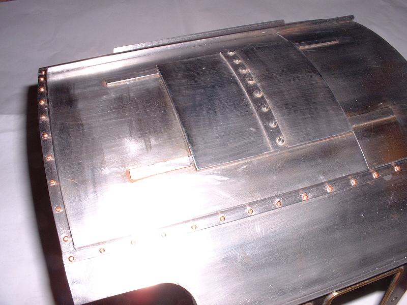
28/11/07 This new photo replaces the one taken on 25/11 and shows the completed cab roof with the dummy hatch and runners, and all the rain strips rivetted into place. It proved quite tricky to bend the rear rain strip across the curve of the roof. The overall end result is quite pleasing and I think was worth the effort - although Doug Hewson's cab kit doesn't seem quite so expensive now!
30/11/07 The next task is to finalise the fitting of the boiler cladding so that I can trim the running boards and spectacle plates to match. I also need to sort out the ashpan so that it fits close under the firebox, and I plan to make cladding for the boiler backhead - Ted has already done this for his model and has offered to lend me the pattern that he made to shape the sheet metal over. The main problem with the cladding is to decide how best to close or cover the gap between the upper throatplate casting and the boiler and/or firebox cladding, as described on 20/9 above. Richard R tells me that he has seen the cab kit from Model Engineers Laser and it looks good value at Ł56 for the Zintec version, although the plates are supplied flat and so need bending to shape. He also alerted me to the fact that Doug Hewson has updated his website with details of a new set of parts and drawings for a 5" Britannia, which I'm sure will be very detailed and accurate.
 3/12/07
I've decided to fit the upper throatplate casting close up behind the boiler cladding, leaving a gap at the top of the firebox cladding which I'll fill by soldering a strip of 1/16" brass onto the exposed flange. This will enable me to fit the rear boiler band in the correct position (see 20/9 above). I've started making little L-shaped brackets from 1/4" brass bar, screwed into the original holes from underneath and carrying new M3 threaded holes to screw the firebox cladding into. The photo shows the cladding screwed to the first two of these brackets. I spent some time thinning down the firebox lagging around some high spots on the upper sides and top, and this has given a better fit. I also trimmed about 5mm off the barrel cladding along the front section of the underside and this has given a better fit around the smokebox, although the boiler band is not strong enough to tighten the cladding really firmly and I shall probably fit some sort of screwed closer between the front lower corners. I've decided to solder captive nuts inside the lower throatplate cladding flanges so that I can fit the firebox cladding easily - it would otherwise be impossible to slide on and off when the washout plugs have been recessed into the lagging (see 26/9 above).
3/12/07
I've decided to fit the upper throatplate casting close up behind the boiler cladding, leaving a gap at the top of the firebox cladding which I'll fill by soldering a strip of 1/16" brass onto the exposed flange. This will enable me to fit the rear boiler band in the correct position (see 20/9 above). I've started making little L-shaped brackets from 1/4" brass bar, screwed into the original holes from underneath and carrying new M3 threaded holes to screw the firebox cladding into. The photo shows the cladding screwed to the first two of these brackets. I spent some time thinning down the firebox lagging around some high spots on the upper sides and top, and this has given a better fit. I also trimmed about 5mm off the barrel cladding along the front section of the underside and this has given a better fit around the smokebox, although the boiler band is not strong enough to tighten the cladding really firmly and I shall probably fit some sort of screwed closer between the front lower corners. I've decided to solder captive nuts inside the lower throatplate cladding flanges so that I can fit the firebox cladding easily - it would otherwise be impossible to slide on and off when the washout plugs have been recessed into the lagging (see 26/9 above).
6/12/07
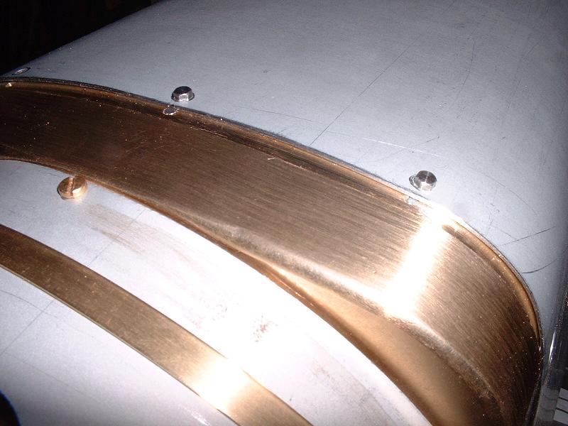
I've completed the modifications to the throatplate casting. I soldered a tapered strip of brass to fill the gap on the rear flange in front of the firebox cladding, and I've also soldered thin strips of brass onto the top of the throatplate to fill slight depressions on either side of the centreline, one of which can be seen faintly in the photo above about halfway between the two bolt heads. All the throatplates seem to have been machined with this slight fault - I checked the stock when I last visited Daventry to see if I could find a better one. After a lot of filing I now have a pretty smooth top to the throatplate, and I've also increased the radius somewhat along the front edge - not as much as on the prototype, which would involve removing a lot of brass and might make it difficult to get
the two sides to match, but an improvement on the rather tight curve as supplied.
- not as much as on the prototype, which would involve removing a lot of brass and might make it difficult to get
the two sides to match, but an improvement on the rather tight curve as supplied.
7/12/07 I've started to attach the fittings to the firebox cladding. The washout plugs should really be flush with the cladding rather than having a protruding rim, so I tried soldering one of the plugs to the rear face of the cladding. However, it didn't look particularly good and the heat from the flame discoloured the Zintec, which can't be rubbed down without removing the zinc coating, so I reverted to glueing them into the holes as per the instructions. I didn't think that the rudimentary firebox steps supplied looked very good, so I made a new one from sheet brass with the authentic dimples as shown in the photograph. The dimples were surprisingly easy to make - I marked out and centre punched the positions on the back of the plate, then hammered each dimple using the centre punch with a 1/16" rivet snap as an anvil. They match the tender steps that I bought from Doug Hewson quite nicely. I'll make similar steps for the front of the running boards in due course. The challenge now is to make a step for the other side of the firebox with matching dimples!
 10/12/07
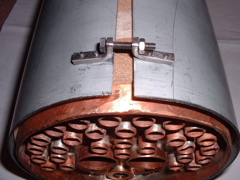
I've made a strong clamp for the front underside of the boiler cladding, as shown in the photograph. The M4 bolt head is slotted so that it can be tightened with a screwdriver after the boiler is fitted to the smokebox, and this pulls the cladding down much more firmly onto the smokebox flange than is possible with the relatively flimsy boiler bands. The fit of the cladding to the smokebox now looks good, although the Zintec is somewhat thicker than the brass cladding that the flange was obviously designed for. I've also made the second firebox step (with dimples that are a perfect mirror image of those on the first one!), and I've soldered nuts to the inside of the lower throatplate cladding so that this can be fitted after the firebox cladding is in place. This completes the work on the existing cladding, apart from attaching handrails, steps and pipe conduits, and the next jobs are to sort out the ashpan (described under kit 15), fit the running boards (described under kit 18), fit the spectacle plates and then make cladding for the backhead. Ted showed me a photo of his backhead cladding and it improves the appearance enormously.
10/12/07
I've made a strong clamp for the front underside of the boiler cladding, as shown in the photograph. The M4 bolt head is slotted so that it can be tightened with a screwdriver after the boiler is fitted to the smokebox, and this pulls the cladding down much more firmly onto the smokebox flange than is possible with the relatively flimsy boiler bands. The fit of the cladding to the smokebox now looks good, although the Zintec is somewhat thicker than the brass cladding that the flange was obviously designed for. I've also made the second firebox step (with dimples that are a perfect mirror image of those on the first one!), and I've soldered nuts to the inside of the lower throatplate cladding so that this can be fitted after the firebox cladding is in place. This completes the work on the existing cladding, apart from attaching handrails, steps and pipe conduits, and the next jobs are to sort out the ashpan (described under kit 15), fit the running boards (described under kit 18), fit the spectacle plates and then make cladding for the backhead. Ted showed me a photo of his backhead cladding and it improves the appearance enormously.
 4/1/08
I've decided to remove the four lugs from each spectacle plate (see photo at 14/9/07 above) and solder the plates to the cab sides. The lugs project slightly beyond the edge of the plate, and don't allow the outer edge of the plate to be trimmed to fit snugly inside the cab side. They also look a bit untidy when viewed from inside the cab. The picture shows the first plate trimmed and clamped to the cab ready for soldering. Note the improvised toolmaker's clamp - I do have some proper ones, but I don't like subjecting them to the blowtorch. The front of the cab side will need bevelling and trimming back a little after soldering, particularly near the top corner where it overhangs the spectacle plate. I'll trim the inner edges when I have fitted both plates, to ensure that they match as closely as possible on the two sides.
4/1/08
I've decided to remove the four lugs from each spectacle plate (see photo at 14/9/07 above) and solder the plates to the cab sides. The lugs project slightly beyond the edge of the plate, and don't allow the outer edge of the plate to be trimmed to fit snugly inside the cab side. They also look a bit untidy when viewed from inside the cab. The picture shows the first plate trimmed and clamped to the cab ready for soldering. Note the improvised toolmaker's clamp - I do have some proper ones, but I don't like subjecting them to the blowtorch. The front of the cab side will need bevelling and trimming back a little after soldering, particularly near the top corner where it overhangs the spectacle plate. I'll trim the inner edges when I have fitted both plates, to ensure that they match as closely as possible on the two sides.
5/1/08 I've now soldered the first spectacle plate and filed the joint flush, and it looks neat and feels very strong. However, Paul has warned me that the soft soldered joint may eventually fail due to the expansion and contraction from the heat of the firebox, so I'll think about rivetting some strengthening strips inside the joint, or getting some TIG spot welds added to strengthen it. I would have silver-soldered the joint, but for the fact that it would melt the soft solder filling that I've already applied to the countersunk screws on the cab side.
 7/1/08
I've managed to silver solder the top and bottom inner corners of the spectacle plates, which should avoid any risk of the joint cracking. I've fitted the second plate and filed the inner edges down to fit around the firebox cladding. This involved removing several mm of material, and the inner edges of the window frames and the inner injector valve hole are now almost touching the cladding. With hindsight I could have removed more metal from the outer edges before fitting them to the cab sides, to centralise the windows better. The other problem that I can foresee is that the steel firebox cladding is quite springy and is pushing against the spectacle plates, which will make it very difficult to slide the cab on after painting without scratching the paint on the firebox.
7/1/08
I've managed to silver solder the top and bottom inner corners of the spectacle plates, which should avoid any risk of the joint cracking. I've fitted the second plate and filed the inner edges down to fit around the firebox cladding. This involved removing several mm of material, and the inner edges of the window frames and the inner injector valve hole are now almost touching the cladding. With hindsight I could have removed more metal from the outer edges before fitting them to the cab sides, to centralise the windows better. The other problem that I can foresee is that the steel firebox cladding is quite springy and is pushing against the spectacle plates, which will make it very difficult to slide the cab on after painting without scratching the paint on the firebox.
8/1/08 The next step is to fit the reverser gearbox and the cardon shaft that connects it to the reverser screw on the weighshaft. I photographed most of the gearbox parts on 15 and 17/9/07 above and described how I assembled it after removing some material from the nylon gears to make them turn smoothly. The drive shaft on the gearbox projects quite a way forward and would place the universal joint halfway through the hole in the spectacle plate, which wouldn't look good (although the hole is big enough to accommodate it), so I moved the shaft back by 8mm so that its shoulder was just in front of the gearbox, making a new dimple for the worm gear grubscrew. I'll trim the rear end flush later. I still had to remove about 6mm from the cardon shaft to make it fit. The cardon shaft rubs against the front edge of the firebox cladding and I'll cut a small notch out of the cladding to fix this. I'll then fit the cardon shaft cover on the running board, which will cover this notch - I'll probably trim off the flanges from the cover plate and solder it in place, since it doesn't look very tidy as it is.
 9/1/08
I ended up filing quite a large wedge out of the firebox cladding to get the cardon shaft to run freely, and also extended the cutout in the running board further back. The reverser handle now raises and lowers the valve gear very smoothly. I modified the cardon shaft cover by trimming the flanges off all the way round the raised section, and moved this further back to line up with the rear of the cutout in the running board. I then filled the front half of the cutout with a strip of steel and soldered the cover to the running board. This looks a lot neater than bolting the large flange on top of the running board, and with a bit of wiggling the running board can still be removed without removing the cardon shaft first. The next job is to fit the handrails, pipe covers and steps to the cladding.
9/1/08
I ended up filing quite a large wedge out of the firebox cladding to get the cardon shaft to run freely, and also extended the cutout in the running board further back. The reverser handle now raises and lowers the valve gear very smoothly. I modified the cardon shaft cover by trimming the flanges off all the way round the raised section, and moved this further back to line up with the rear of the cutout in the running board. I then filled the front half of the cutout with a strip of steel and soldered the cover to the running board. This looks a lot neater than bolting the large flange on top of the running board, and with a bit of wiggling the running board can still be removed without removing the cardon shaft first. The next job is to fit the handrails, pipe covers and steps to the cladding.
11/1/08
I've started fitting the handrails to the boiler cladding. The two holes in each side of the firebox have been drilled and tapped 6BA (there is also a superfluous third hole at the rear on the right hand side), but the holes in the boiler cladding have not been drilled. The stanchions do not screw down quite flush into the 6BA holes because they have a slight shoulder at the end of the thread, so I drilled the holes out and fitted nuts on the inside, trimming the threads to length and cutting the lagging to clear the nuts. I marked the positions for the barrel stanchions by sliding the clevises from the regulator rods onto the handrail and pressing them onto the cladding with the handrail held in a straight line through the smokebox and firebox stanchions. I positioned the front stanchions 140mm back from the front of the cladding, and the  others at intervals of 131mm
- I think this is about right.
others at intervals of 131mm
- I think this is about right.
14/1/08 I've completed the boiler handrails - I lowered the front firebox stanchions by 1.5mm by slotting their holes to reduce the bend at this point, and the rails run straight from smokebox to firebox front, then curve gently downwards and inwards along the firebox sides. I also fitted the firebox steps that I made previously (see 7/12/07 above) with 10BA bolts. I then fitted the three pipe covers along the left hand side of the boiler and firebox - these cover the blower and vacuum brake ejector pipes on the prototype, and I'll fit dummy pipes in the visible sections later. I shortened the rear of the middle cover by about 13mm and moved the rear cover forward to meet it - this gives a better fit around the front of the firebox, and I think positions the rear end more accurately. I trimmed all the bolt flanges down and used small-headed M3 bolts to fix the covers. This more or less completes the platework, apart from filling superfluous holes and adding the cab rivets, and I'll start on the pipework next.
 15/1/08
I polished up the steam manifold and fitted it to the firebox. It screws quite well down into the bush, but not right to the shoulder because of the thickness of the cladding. It needs a thick washer and/or some PTFE tape or Foliac on the thread. There are six steam pipes - the two injectors on the left and right rear fittings, the blower on the left-hand end, the pressure gauge on the left front, the steam brake on the centre front, and the whistle on the right front. There are also blanking plugs at the centre rear for the dummy manifold cut-off valve with a rod extending back under the cab roof, and at the right-hand end for the dummy steam heating valve. The latter blanking plug, not shown in the photo, has a very large hexagonal section which looks unsightly and catches on the cladding, so I'll trim this down. I bent one of the injector pipes to shape and fitted it - it's quite difficult to make a tight bend so close to the end fitting, and the other injector pipe needs an even tighter bend. I think it might be easier to buy a length of copper tube and bend the pipes to shape and cut them to length before soldering on the end fittings - this would also ensure that the lengths are exactly right. I did buy a pipe bending tool from Chronos which works nicely but only produces a fixed 1" radius, so it's not much use in tight corners. I see that they also sell tube bending springs that slip over the outside of the pipe, but these obviously can't be used when the end fittings are already soldered on.
15/1/08
I polished up the steam manifold and fitted it to the firebox. It screws quite well down into the bush, but not right to the shoulder because of the thickness of the cladding. It needs a thick washer and/or some PTFE tape or Foliac on the thread. There are six steam pipes - the two injectors on the left and right rear fittings, the blower on the left-hand end, the pressure gauge on the left front, the steam brake on the centre front, and the whistle on the right front. There are also blanking plugs at the centre rear for the dummy manifold cut-off valve with a rod extending back under the cab roof, and at the right-hand end for the dummy steam heating valve. The latter blanking plug, not shown in the photo, has a very large hexagonal section which looks unsightly and catches on the cladding, so I'll trim this down. I bent one of the injector pipes to shape and fitted it - it's quite difficult to make a tight bend so close to the end fitting, and the other injector pipe needs an even tighter bend. I think it might be easier to buy a length of copper tube and bend the pipes to shape and cut them to length before soldering on the end fittings - this would also ensure that the lengths are exactly right. I did buy a pipe bending tool from Chronos which works nicely but only produces a fixed 1" radius, so it's not much use in tight corners. I see that they also sell tube bending springs that slip over the outside of the pipe, but these obviously can't be used when the end fittings are already soldered on.
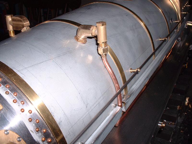 16/1/08
I fitted the left hand top feed pipe, cutting and filing the boiler fitting down to a more realistic shape - the original is shown on the other side in the photo for comparison. The shape is still not quite like the prototype, but at least it's more plausible. The pipe bends round the boiler and back along the top of the running board, down the front of the firebox and back along the ashpan to position the injector roughly in the centre of the ashpan side, as on the prototype. The pipe is perhaps a little too long and I may shorten it once I have the injector available.
16/1/08
I fitted the left hand top feed pipe, cutting and filing the boiler fitting down to a more realistic shape - the original is shown on the other side in the photo for comparison. The shape is still not quite like the prototype, but at least it's more plausible. The pipe bends round the boiler and back along the top of the running board, down the front of the firebox and back along the ashpan to position the injector roughly in the centre of the ashpan side, as on the prototype. The pipe is perhaps a little too long and I may shorten it once I have the injector available.
20/1/08 I've fitted the injector steam pipe from the manifold to the second injector steam valve. This pipe was too long, so I cut the ferrule off one end and hence was able to slide on the pipe bending spring that I bought from Chronos at Alexandra Palace. However, it still proved difficult to get a tight enough bend so close to the top ferrule. In the end I made a new pipe, forming the bend with the spring before trimming it and silver soldering the ferrules, and this worked well, although it's quite difficult to remove the spring after forming a tight bend. I'll fit the Doug Hewson carriage heating valve casting that I bought at Alexandra Palace next.
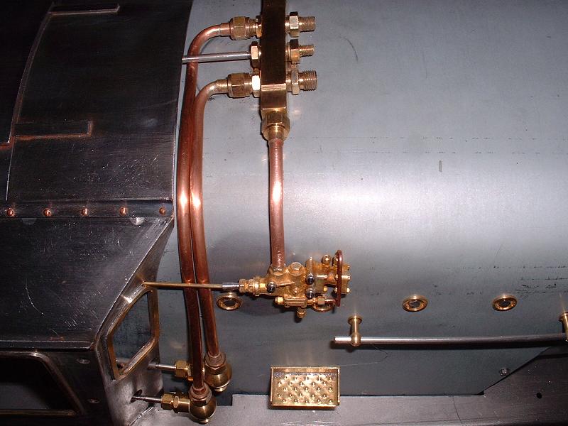 21/1/08
The photo shows the carriage heating valve casting which I secured with 3 10BA bolts tapped into the firebox cladding. I made the control spindle from a short piece of 1/8" rod tapped M3 into the casting and a length of 1/16" rod passing through a hole above the cab window. A scale handwheel is provided. I fitted the inlet pipe to the manifold with a short length of threaded brass, since the connector provided is rather large. I removed the bush for the steam lance from the casting, because it's clear from the photos that the Britannias were not fitted with these. I still need to fit the outlet pipe, overflow pipe and pressure gauge pipe - it's not clear how the outlet pipe attaches to the front flange of the casting, so I've emailed Doug to ask.
21/1/08
The photo shows the carriage heating valve casting which I secured with 3 10BA bolts tapped into the firebox cladding. I made the control spindle from a short piece of 1/8" rod tapped M3 into the casting and a length of 1/16" rod passing through a hole above the cab window. A scale handwheel is provided. I fitted the inlet pipe to the manifold with a short length of threaded brass, since the connector provided is rather large. I removed the bush for the steam lance from the casting, because it's clear from the photos that the Britannias were not fitted with these. I still need to fit the outlet pipe, overflow pipe and pressure gauge pipe - it's not clear how the outlet pipe attaches to the front flange of the casting, so I've emailed Doug to ask.
23/1/08 Doug has replied with a photo of one of his models, so I'll try to fabricate a pipe elbow. I've been looking at Modelworks' instructions for the remaining manifold pipes and I can see a few issues. The 3/32" steam brake and 5/32" pressure gauge pipes should be OK - they bend back to the left from the front of the manifold and I think are thin enough to slip under the cab roof. The whistle pipe is 3/16" thick and is shown bending back to the right of the manifold, but the injector pipes prevent it feeding back under the cab roof. There is no equivalent pipe on the prototype, since the steam feed for the whistle comes from the smokebox, and the whistle is operated by a piece of string (or similar) running inside the hollow handrail. There's also an issue with the whistle valve itself - the drawings show the 3/16" inlet pipe going into the 5/32" pipe fitting on the underside of the whistle valve, with the valve fitted at a strange angle to receive it, but I think the input should go into the elbow on the end of the valve, with a 5/32" pipe from the valve to the whistle - this latter pipe has not yet been supplied. The feed pipe for the blower is also an issue - it is shown bending back from the left hand end of the manifold, then under the cab roof or perhaps through a notch in the spectacle plate, across the top of the firebox and down to a valve below the two injector handwheels on the lower right of the firebox. On scratch-built models the blower valve is usually mounted in front of the cab on the lower left of the firebox cladding, where the duplex valve is fitted on the prototype. I'll mull over these questions for a day or two before starting to bend the pipes.
25/1/08 I've silver-soldered a pipe elbow to the carriage heating valve and fitted the outlet pipe. Harry L sent me this photo of the manifold of a superb 5 " Britannia that we saw at the Harrogate show two years ago. I believe that this is the correct pipe layout, so my plan now is to block off the front right manifold outlet using one of the two apparently superfluous blanking plugs provided, fit a thin (3/32") pipe for the pressure gauge from the front centre outlet, and fit a 3/16" pipe to the front left and run this down the front of the cab and use it with a suitable union to feed both the whistle and the steam brake. I'll then run the blower pipe from the left end outlet down the side of the firebox to a dummy duplex valve, then into the cab and fit the blower valve above the reverser gearbox. This picture shows this pipework on 70000 - I think the blower pipe runs from the top of the duplex valve into the driver's blower valve in the cab, and the outlet pipe from the blower valve runs forward from the cab under the duplex valve and into the trunking, along with the two ejector feeds from the duplex valve. I'm not sure what the other pipe coming down from the manifold is for - possibly sanders and/or drain cocks - but it has a tee running into the cab at the top which could perhaps be for the pressure gauge or the steam brake.
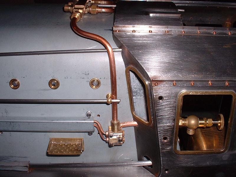 28/1/08
I've started making a dummy duplex valve - I cannibalised the dummy steam heating valve to make the body, and drilled a piece of 8mm brass rod to take the pipes from the manifold and to the blower valve. I'll add dummy ejector pipes and control rods to the duplex valve. I also cut a notch in the spectacle plate for the regulator rod - I moved this a bit higher up, halfway round the curve of the firebox cladding, and I'll make a new bracket for the regulator lever later, when I make the cladding for the boiler backhead.
28/1/08
I've started making a dummy duplex valve - I cannibalised the dummy steam heating valve to make the body, and drilled a piece of 8mm brass rod to take the pipes from the manifold and to the blower valve. I'll add dummy ejector pipes and control rods to the duplex valve. I also cut a notch in the spectacle plate for the regulator rod - I moved this a bit higher up, halfway round the curve of the firebox cladding, and I'll make a new bracket for the regulator lever later, when I make the cladding for the boiler backhead.
30/1/08 The photo shows the blower pipes and duplex valve - I just need to add dummy control rods running from the back of the duplex valve to the cab. I've positioned the blower valve above the reverser gearbox, where it will be easy to reach. I've used one of the 90 degree globe valves which were probably intended for the water feeds to the injectors (although the ISO diagrams show straight-through ones - see the problem list below). I plan to buy different water valves with a 90 degree on-off movement, so this valve is effectively spare. The next job is to run the pipe from this blower valve to the smokebox - I'll need to make a longer one, since I've positioned the valve on the opposite side of the cab.
 31/1/08
Modelworks do now have the name and number plates in stock, and I asked them to send me mine. They look very nice indeed - the photo doesn't do them justice (probably a jpeg artefact as a result of reducing the picture size). Modelworks have not supplied the other plates, which is disappointing since they were shown in the brochure photograph, but they can be ordered directly from the maker for Ł48 - the photo shows his details. I'll wait to check the tender number etc on 70013 at Loughborough before ordering them. I've also received this photo from Rod A showing the superb improvements that he's made to his firebox - six correctly placed flush-mounted washout plugs on the left-hand side, further washout plugs lower down and on the rear of the boiler cladding, mudhole doors and steps (all from Doug Hewson), boiler bands around the firebox, copper backhead cladding, and simulated joints between the firebox cladding plates. Note also the sandbox lids and the speedometer fitting on the rear crank, which he made from scratch. He tells me that he's also made a lot of improvements to the cab. I shall have to revisit my firebox!
31/1/08
Modelworks do now have the name and number plates in stock, and I asked them to send me mine. They look very nice indeed - the photo doesn't do them justice (probably a jpeg artefact as a result of reducing the picture size). Modelworks have not supplied the other plates, which is disappointing since they were shown in the brochure photograph, but they can be ordered directly from the maker for Ł48 - the photo shows his details. I'll wait to check the tender number etc on 70013 at Loughborough before ordering them. I've also received this photo from Rod A showing the superb improvements that he's made to his firebox - six correctly placed flush-mounted washout plugs on the left-hand side, further washout plugs lower down and on the rear of the boiler cladding, mudhole doors and steps (all from Doug Hewson), boiler bands around the firebox, copper backhead cladding, and simulated joints between the firebox cladding plates. Note also the sandbox lids and the speedometer fitting on the rear crank, which he made from scratch. He tells me that he's also made a lot of improvements to the cab. I shall have to revisit my firebox!
2/2/08 I've made a new pipe to run from my repositioned blower valve to the fitting on the right-hand side of the smokebox. I routed it down from the valve, forward through a slot in the spectacle plate under the left hand running board, across under the boiler in front of the firebox, and along under the right hand running board to the smokebox fitting. It's just possible to wiggle it in and out without removing the boiler. I've now used up most of the 5ft length of 3/16" pipe that I bought, but I should be able to cannibalise the old blower pipe for any further new sections. The pipe from the smokebox fitting to the chimney has not been supplied, but I imagine that this is just a simple piece of pipe with the open end positioned alongside the blastpipe nozzle and pointing upwards into the petticoat pipe.
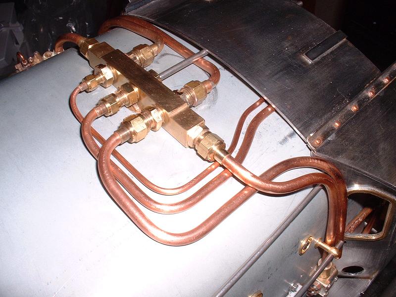 4/2/08
I've changed my mind again about the pipe routeing and come up with the arrangement shown in this photo. The 3/32" pipe from the front right of the manifold is for the steam brake, and runs back over the firebox and down the backhead to the brake valve somewhere near the regulator - I still need to decide exactly where to position it. The pipe supplied is far too long. The 5/32" pipe from the middle front is for the pressure gauge, routed across under the cab roof to the right hand side of the firebox, where I'll solder a length of 3/32" pipe into it to form the syphon loop under the pressure gauge - this holds some condensed water to prevent the steam damaging the pressure gauge. I've chosen to put the pressure gauge to the right of the water gauges as on the prototype, but the pipe supplied is not long enough for this. The 3/16" pipe from the front left is for the whistle - I'll make a T junction above the cab window and feed the pipe through a notch in the spectacle plate and over the top of the firebox to the whistle valve on the right hand side. The downward continuation below the T junction to the running board will be a dummy, for which I'll probably use 3/32" pipe.
4/2/08
I've changed my mind again about the pipe routeing and come up with the arrangement shown in this photo. The 3/32" pipe from the front right of the manifold is for the steam brake, and runs back over the firebox and down the backhead to the brake valve somewhere near the regulator - I still need to decide exactly where to position it. The pipe supplied is far too long. The 5/32" pipe from the middle front is for the pressure gauge, routed across under the cab roof to the right hand side of the firebox, where I'll solder a length of 3/32" pipe into it to form the syphon loop under the pressure gauge - this holds some condensed water to prevent the steam damaging the pressure gauge. I've chosen to put the pressure gauge to the right of the water gauges as on the prototype, but the pipe supplied is not long enough for this. The 3/16" pipe from the front left is for the whistle - I'll make a T junction above the cab window and feed the pipe through a notch in the spectacle plate and over the top of the firebox to the whistle valve on the right hand side. The downward continuation below the T junction to the running board will be a dummy, for which I'll probably use 3/32" pipe.
7/2/08 I've changed my mind yet again - I hope that nobody is copying my every move! I decided that I might as well use the 3/32" pipe running down from the T junction as the steam brake feed rather than a dummy, and revert to a blanking plug on the front right hand manifold outlet. Although I do have a photo showing a Britannia with a pipe running to the left from this outlet, it's of 70053 'Moray Firth' which would have had the BR1D high-sided tender, and I suspect that this feed may be for the steam-powered coal pusher fitted to that type of tender. I've had some trouble silver soldering the three pipes into a short length of 8mm brass rod to form the T junction, but after several abortive attempts I have now succeeded.
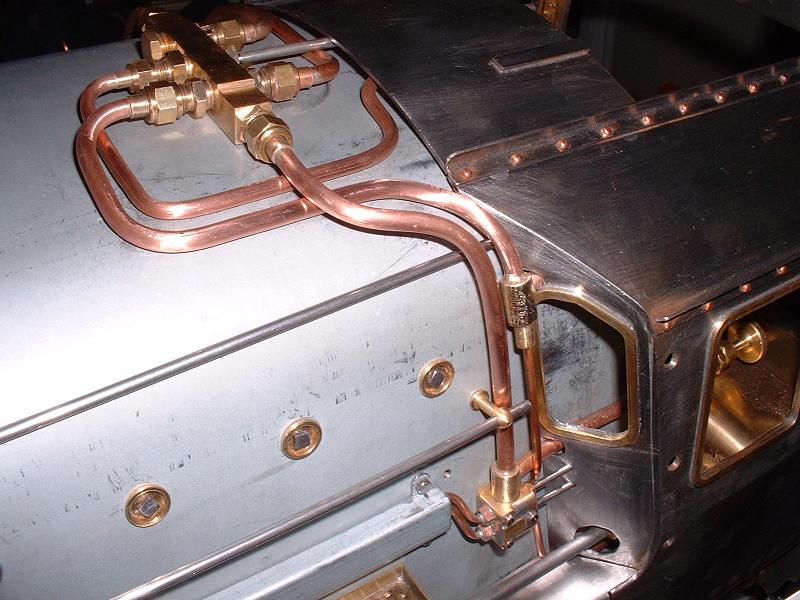 10/2/08
This photo shows the final layout of the manifold pipes. The brass T junction in front of the spectacle plate feeds the 3/16" pipe for the whistle which runs into the cab and across the top of the firebox to the whistle valve position on the right hand side, and the 3/32" pipe for the steam brake which runs down under the running board and back into the cab. I've left the ends of these pipes and the pressure gauge pipe unfinished pending the fitting of the backhead cladding and the final positioning of their respective fittings. Note the dummy control spindles for the duplex valve, made from 3/32" stainless steel rod. I'll also fit a dummy blower outlet pipe running from the spectacle plate under the duplex valve and into the trunking. I'm not going to fit the rest of the injector pipework until I have the injectors to check the sizing, so the next major task is to make the backhead cladding and fit the regulator lever and the other cab fittings.
10/2/08
This photo shows the final layout of the manifold pipes. The brass T junction in front of the spectacle plate feeds the 3/16" pipe for the whistle which runs into the cab and across the top of the firebox to the whistle valve position on the right hand side, and the 3/32" pipe for the steam brake which runs down under the running board and back into the cab. I've left the ends of these pipes and the pressure gauge pipe unfinished pending the fitting of the backhead cladding and the final positioning of their respective fittings. Note the dummy control spindles for the duplex valve, made from 3/32" stainless steel rod. I'll also fit a dummy blower outlet pipe running from the spectacle plate under the duplex valve and into the trunking. I'm not going to fit the rest of the injector pipework until I have the injectors to check the sizing, so the next major task is to make the backhead cladding and fit the regulator lever and the other cab fittings.
12/2/08 I've made a start on the backhead cladding, using a piece of 0.7mm sheet brass. I've made the crease below the water gauges using my bending brake, and drilled and filed the four 13mm holes for the water gauge bushes. The next and much more difficult step is to make a wooden former and anneal and hammer over the edges of the brass sheet to fit inside the firebox cladding. Rod A sent me this photo of the former that he made for his backhead cladding.
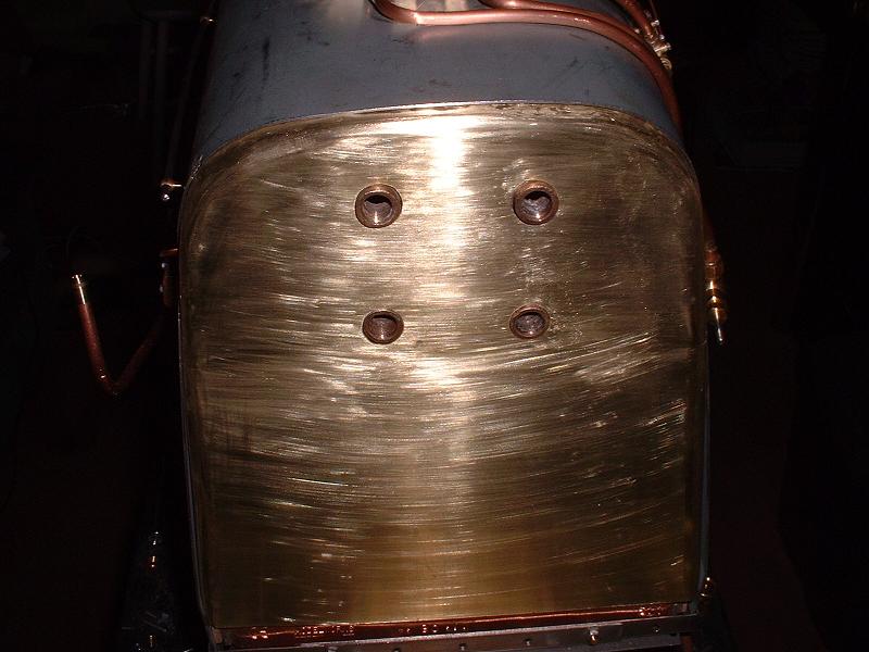 14/2/08
I've successfully bent the two sides of the backhead cladding from the bottom up to the level of the horizontal crease. I didn't make a wooden former for this part - I used a strip of steel that I had previously bent to a right angle in the bending brake as a former. This had a curve of a few mm radius on the angle and it gave a nice smooth curve to the cladding. I marked out each side, allowing for the thickness of the brass plus a couple of mm for the radius of the bend and annealed the brass and then clamped it between the steel former and another plate. It was then easy to tap the brass down over the bend using a short piece of wood to spread the hammer blows. I now need to tackle the tricky part around the top of the firebox. I've heard on the grapevine that Modelworks have a schedule listing most of the outstanding items for completion by the end of March, including lost wax castings for the dome and the AWS battery box.
14/2/08
I've successfully bent the two sides of the backhead cladding from the bottom up to the level of the horizontal crease. I didn't make a wooden former for this part - I used a strip of steel that I had previously bent to a right angle in the bending brake as a former. This had a curve of a few mm radius on the angle and it gave a nice smooth curve to the cladding. I marked out each side, allowing for the thickness of the brass plus a couple of mm for the radius of the bend and annealed the brass and then clamped it between the steel former and another plate. It was then easy to tap the brass down over the bend using a short piece of wood to spread the hammer blows. I now need to tackle the tricky part around the top of the firebox. I've heard on the grapevine that Modelworks have a schedule listing most of the outstanding items for completion by the end of March, including lost wax castings for the dome and the AWS battery box.
15/2/08 I made a former for the top half of the cladding from a piece of softwood and hammered the edges over it, stopping frequently to re-anneal the brass. I then filed the curves to remove most of the irregularities. I've replaced yesterday's photograph to show the result. There are a few remaining blemishes, but I don't think it's too bad considering that it's my first attempt at panel-beating. The next step is to bolt it to the firebox cladding, then make the remaining holes, fit the firebox doors and make new more realistic brackets for the regulator and the injector and whistle valves.
17/2/08 I've cut the opening for the fire hole and fitted the fire hole doors that I modified almost a year ago in kit 18a - they now slide very smoothly with the cladding to support them. I've also fitted the two clack valves. I'll fit brackets for the injector valves, pressure gauge and whistle valve directly to the cladding. The regulator bracket will need to be firmly fixed to the bushes on the firebox but these are not flush with the cladding, so I'll probably fix some sort of supporting plate to them under the cladding.
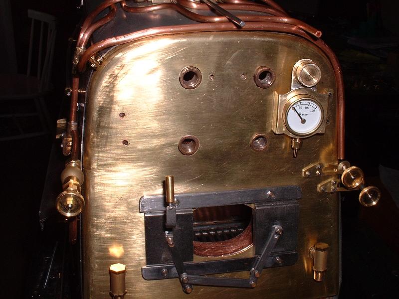 21/2/08
I've made brackets for the injector valves and the boiler pressure gauge and dummy carriage heating pressure gauge, which I think all look reasonably realistic when compared with 70000. The pressure gauge is a firm push fit in the hole in the bracket - I didn't want to just leave it perched on the end of its pipe. I'll fit the whistle valve to the right of the pressure gauge and then finish the pipework - I'll join a length of 3/32" pipe into the 5/32" pressure gauge pipe on top of the firebox and form a siphon loop down to the connector on the gauge.
21/2/08
I've made brackets for the injector valves and the boiler pressure gauge and dummy carriage heating pressure gauge, which I think all look reasonably realistic when compared with 70000. The pressure gauge is a firm push fit in the hole in the bracket - I didn't want to just leave it perched on the end of its pipe. I'll fit the whistle valve to the right of the pressure gauge and then finish the pipework - I'll join a length of 3/32" pipe into the 5/32" pressure gauge pipe on top of the firebox and form a siphon loop down to the connector on the gauge.
24/2/08 I've fitted the whistle valve and the pressure gauge pipe. I initially mounted the whistle valve immediately to the right of the pressure gauge bracket, but it looked rather obtrusive - I'm not sure why it needs to be so long - so I moved it to the side of the firebox where it will be out of the way. I'm next going to fabricate a new bracket for the regulator lever, more in keeping with the prototype. I've extended the clevis for the top of the regulator lever with a 13mm length of 3/16" brass rod drilled and tapped M3, so that I can move the regulator lever back a little and avoid the forks of the clevis catching on the cladding.
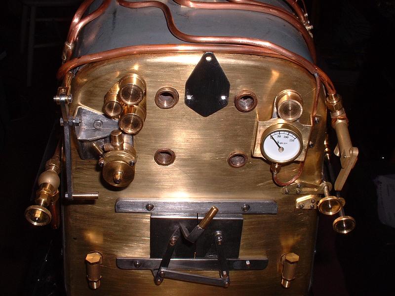 26/2/08
I've made a bracket for the regulator lever from pieces of 16g steel silver soldered together, with a mounting plate for the steam brake valve incorporated. The kit doesn't include anything for the latter but the valve could hardly be left supported just by its thin pipes. I did think of mounting the valve upside down with the lever moving backwards and forwards as on 70000 (the vertical brass handle between the two red ones), but it would be fiddly to operate and in any case it doesn't look quite like the real thing - Dave Noble does an authentic BR steam brake valve. The photo also shows the pressure gauge and whistle valve pipes. I'll also make a brass handle for the regulator lever and a new taller bracket for the manifold shut-off valve.
26/2/08
I've made a bracket for the regulator lever from pieces of 16g steel silver soldered together, with a mounting plate for the steam brake valve incorporated. The kit doesn't include anything for the latter but the valve could hardly be left supported just by its thin pipes. I did think of mounting the valve upside down with the lever moving backwards and forwards as on 70000 (the vertical brass handle between the two red ones), but it would be fiddly to operate and in any case it doesn't look quite like the real thing - Dave Noble does an authentic BR steam brake valve. The photo also shows the pressure gauge and whistle valve pipes. I'll also make a brass handle for the regulator lever and a new taller bracket for the manifold shut-off valve.
28/2/08 I've made the brass handle for the regulator and the new manifold shut-off bracket, and also a new bracket for the three left-hand dummy gauges. I've replaced the last photo to include these. I'll fit the large speedometer gauge to the left of the regulator lever, on a bracket attached to the cab roof. I've bolted the lower sides of the firebox cladding to the backhead cladding, using captive nuts soldered behind the backhead cladding. I'll buy some authentic Gresham and Craven style handwheels for all the cab valves. The dummy manifold valve spindle would be too close to the cab roof to fit a handwheel if I ran it over the pipes, so I'll cut it in half and fit the handwheel to a stub on the bracket. This completes the work on the backhead. We're away on holiday for the next week, and when I get back I'll chase Modelworks for the remaining missing parts - there's not much more that I can do without them.
9/3/08 We're back from a week in the sunshine, just in time for the next depression sweeping in from the Atlantic. It's a while since we've had a chance to go sailing and I just hope that our boat is withstanding the gales on the south coast. I'm within sight of the end now and I've started a list of the remaining jobs at the bottom of this page, which I'll update as I progress. Some of these items I can do while waiting for the remaining parts from Modelworks - I've emailed them today to ask about progress.
11/3/08 I've fitted the right hand top feed pipe, running the pipe along the top of the running board as on the prototype rather than underneath it. I've started to make new doors for the cab, which I'll fix at the front with dummy hinges - the doors provided have an angle at the back which doesn't look quite right, and it's very easy to make new flat ones. I've ordered some chequer plate for the cab floor from Polly, along with a pair of their 90 degree on-off water valves for the injector feeds which I think will be more convenient to operate than the globe valves supplied, and will probably give a higher throughput.
13/3/08 I've completed the first cab door. Polly are out of stock of the water valves at the moment. Although Modelworks haven't replied to my email about the missing parts, Richard P tells me that he chased them recently and was sent the blower pipe, whistle pipe, pipe tee, deflector brackets, reversing stand spacer, vacuum pipe and a temporary dome cover (with a better one apparently being produced). Modelworks are still waiting for the injectors but the water gauge assembly is due shortly, the regulator valve connector and snifter pipes are "in design" and the AWS box is being cast. Richard has also received his safety valves.
 16/3/08
I've fitted the cab doors. I had a letter from Dean at Modelworks yesterday, which I believe he's sent to all the Britannia builders, saying that all the outstanding items apart from the injectors should be available for delivery by mid-April at the latest. He says that they've had great difficulty sourcing the injectors in the quantity they need, but they have now found a supplier who can produce a batch within 12 weeks. This is very unsatisfactory - they've had over 3 years since the kit was launched to procure the injectors, and it's now 6 months since they took the payment for them. I've received the chequer plate for the cab floor from Polly (a company with refreshingly good customer service) and this looks very realistic - I bought 2 pieces of 10" x 2 3/8", which will be sufficient since part of the floor is covered in wooden planks - the plate just covers the rear area and a strip immediately behind the firebox. I'll probably make a drop-in false floor out of thin sheet metal and glue the chequer plate and planks to this. The existing floor really needs to be covered because several of the holes are in the wrong place.
16/3/08
I've fitted the cab doors. I had a letter from Dean at Modelworks yesterday, which I believe he's sent to all the Britannia builders, saying that all the outstanding items apart from the injectors should be available for delivery by mid-April at the latest. He says that they've had great difficulty sourcing the injectors in the quantity they need, but they have now found a supplier who can produce a batch within 12 weeks. This is very unsatisfactory - they've had over 3 years since the kit was launched to procure the injectors, and it's now 6 months since they took the payment for them. I've received the chequer plate for the cab floor from Polly (a company with refreshingly good customer service) and this looks very realistic - I bought 2 pieces of 10" x 2 3/8", which will be sufficient since part of the floor is covered in wooden planks - the plate just covers the rear area and a strip immediately behind the firebox. I'll probably make a drop-in false floor out of thin sheet metal and glue the chequer plate and planks to this. The existing floor really needs to be covered because several of the holes are in the wrong place.
20/3/08 The water valves have arrived from Polly, but I need the missing pipe tee from Modelworks before I can fit them. I've fitted Doug Hewson's carriage heating hose to the front buffer beam. I'll do the same on the tender rear beam and put a photo on the kit 4 page.
26/3/08 In view of the 12 week delay on the injectors, I've bought a pair of Gordon Chiverton injectors (one 24oz and one 16oz) from Polly, and written to Dean at Modelworks inviting him to give me a refund. The GC injectors are a premium brand at Ł37.50 each, compared with the Jubilee at Ł25, but I was advised by Ben P that it's worth paying the extra. I've asked Dean to refund Ł50 on the assumption that they would have provided Jubilee or similar. I bought the last 24oz GC that Polly had in stock - they have more on order. They do have some Jubilee No 4 in stock. Apparently there's some benefit in having the two different sizes, since the smaller 16oz (which has the same physical dimensions) will have less impact on the boiler pressure when running.
10/4/08 Dean phoned me a few days ago in response to my letter about the injectors and agreed to refund me the cost (to Modelworks) of the injectors that they eventually supply, although he couldn't say exactly how much this would be. I've noticed that the pipe nipples on the delivery pipes from the injectors to the boiler top feeds are the standard conical type rather than the flat-ended type needed for injectors, so I'll have to replace these nipples with the ones supplied with the injectors. If this error affects all kits, Modelworks will need to replace the pipes for those not wishing to silver-solder them, so bear this in mind before laboriously bending the pipes to shape. The steam pipes from the steam valves to the injectors do have the correct fittings, at least in my kit. My injectors also need flat-ended nipples on the water inlet pipes, but I'm told that this is a peculiarity of GC injectors and so shoudn't be an issue with the ones that Modelworks eventually supply to other builders. I've been thinking about the positioning of the water valves and I may put them inside the tender rather than under the cab floor, with extended handles sticking up through the rear top plate of the tender. They will be easier to operate in this position, and the pipework under the cab will be much more direct.
14/4/08 I've started fitting the pipework for the injectors. I'll position them both towards the front of the ashpan sides. The right hand one may interfere with the dummy exhaust steam injector, but this is bound to be a bit of a compromise - perhaps what's really needed is a hollowed-out dummy exhaust steam injector to cover the real one! I'll make new water input pipes which just run back under the cab and turn down in front of the rear beam, so that the flexible tubes can hang in a U shape from tender to loco. I can't see how the flexible pipes could be fitted to the unions provided, which point back through the rear beam directly at the tender front beam.
 18/4/08
I've fitted the 24oz injector on the left hand side, as shown in the photograph. The steam pipe runs from the lower/outer of the two valves down through the running board then under the cab floor and across the back of the firebox. I shortened it by a couple of inches, although the extra could have been hidden under the cab floor. I also shortened the output pipe to the top feed to get the injector in the position shown. I made a water feed pipe that simply loops over the pony and down in front of the rear beam, since I'll fit the water valves in the tender. I'll need to trim this pipe to length and support it at the rear end in some way, and I'll probably also change the rear end of the axle pump feed to the same style. I silver-soldered the flat-ended nipples provided with the injector onto each of the three pipes. I noticed quite by chance that the nipple at the other end of the steam pipe was completely blocked with a solidified lump of flux, which I had to drill out, so it's worth blowing through all the pipes to check that they are clear. The injector looks reasonably realistic, although the pipe connections are different on the real thing - note also how the overflow from the injector is piped back to the right hand side so that the fireman can monitor it. A replica of the water valve under the cab would also improve the appearance.
18/4/08
I've fitted the 24oz injector on the left hand side, as shown in the photograph. The steam pipe runs from the lower/outer of the two valves down through the running board then under the cab floor and across the back of the firebox. I shortened it by a couple of inches, although the extra could have been hidden under the cab floor. I also shortened the output pipe to the top feed to get the injector in the position shown. I made a water feed pipe that simply loops over the pony and down in front of the rear beam, since I'll fit the water valves in the tender. I'll need to trim this pipe to length and support it at the rear end in some way, and I'll probably also change the rear end of the axle pump feed to the same style. I silver-soldered the flat-ended nipples provided with the injector onto each of the three pipes. I noticed quite by chance that the nipple at the other end of the steam pipe was completely blocked with a solidified lump of flux, which I had to drill out, so it's worth blowing through all the pipes to check that they are clear. The injector looks reasonably realistic, although the pipe connections are different on the real thing - note also how the overflow from the injector is piped back to the right hand side so that the fireman can monitor it. A replica of the water valve under the cab would also improve the appearance.
21/4/08 I've started fitting the smaller 16oz injector on the right hand side, in the same position as on the left. I shortened the output pipe and fitted the flat-ended nipple, but I had to make up a longer pipe from the steam valve down to the rear of the injector - the one supplied doesn't even reach below the firebox. Unfortunately I made a mess of one of the pipe unions and nipples while silver-soldering, so I can't make up the water inlet pipe - I've asked Polly if they can let me have spares. I'm hoping that the final parts will arrive from Modelworks tomorrow, since they were apparently all packed up ready for dispatch on Friday.
I've started a new page for the final kit, since this page has become rather long.
| Next Kit | Previous Kit | Index |
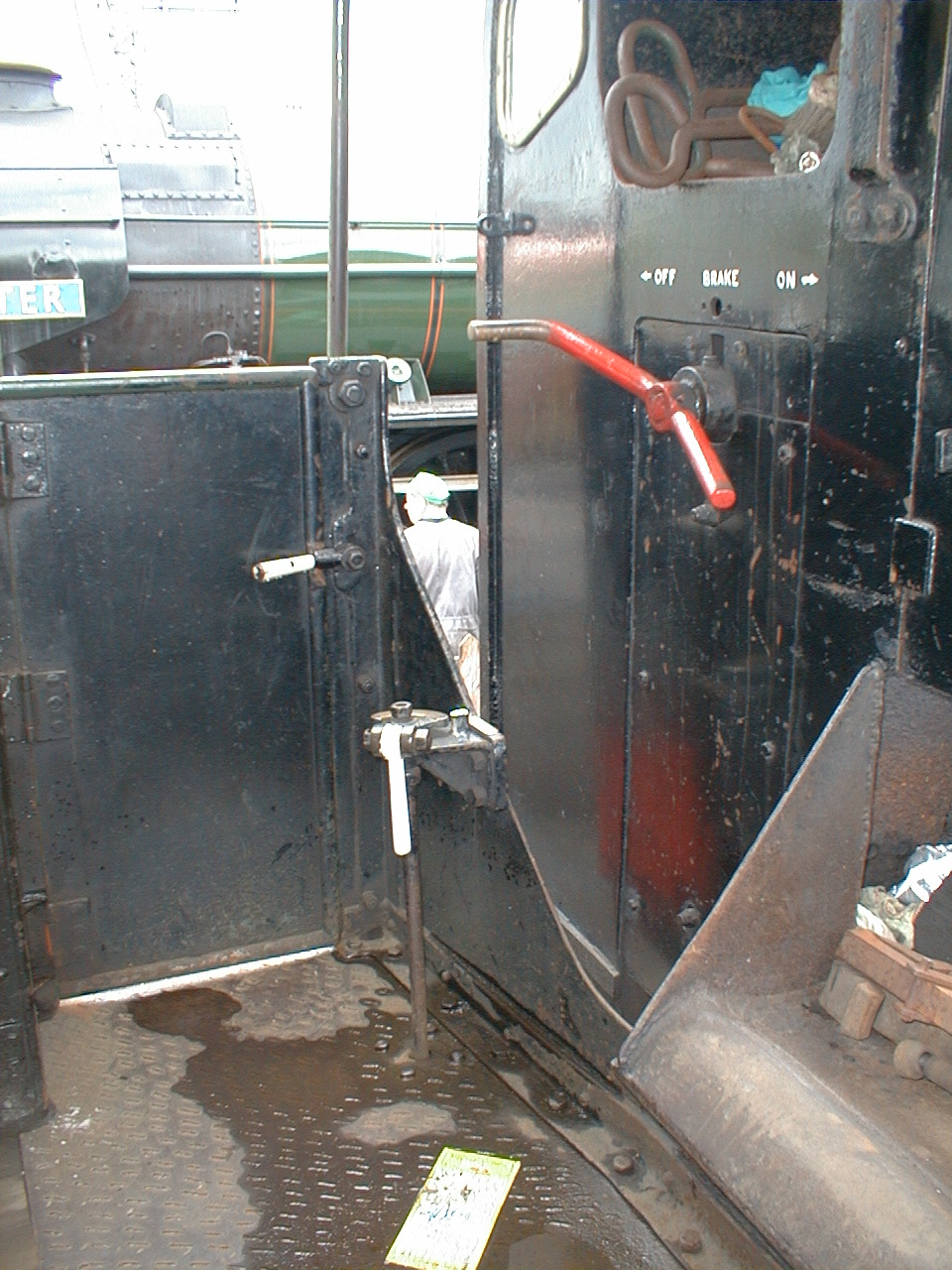
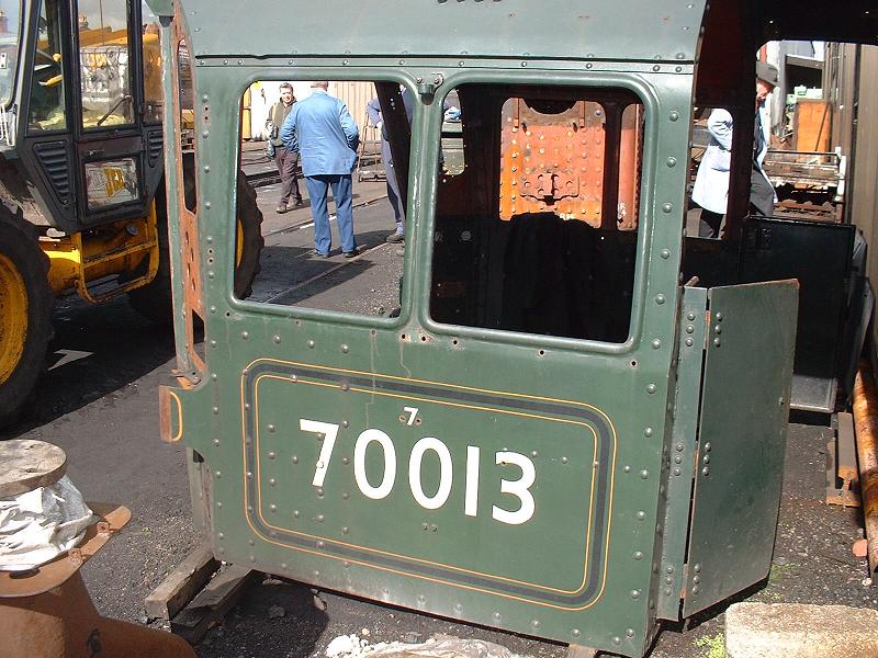
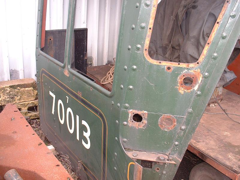
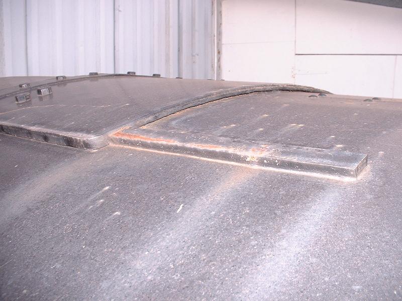
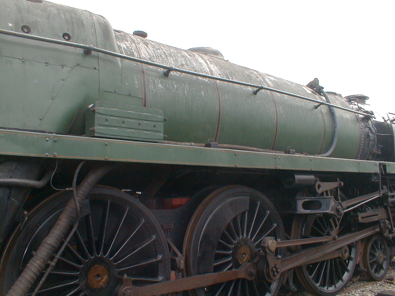
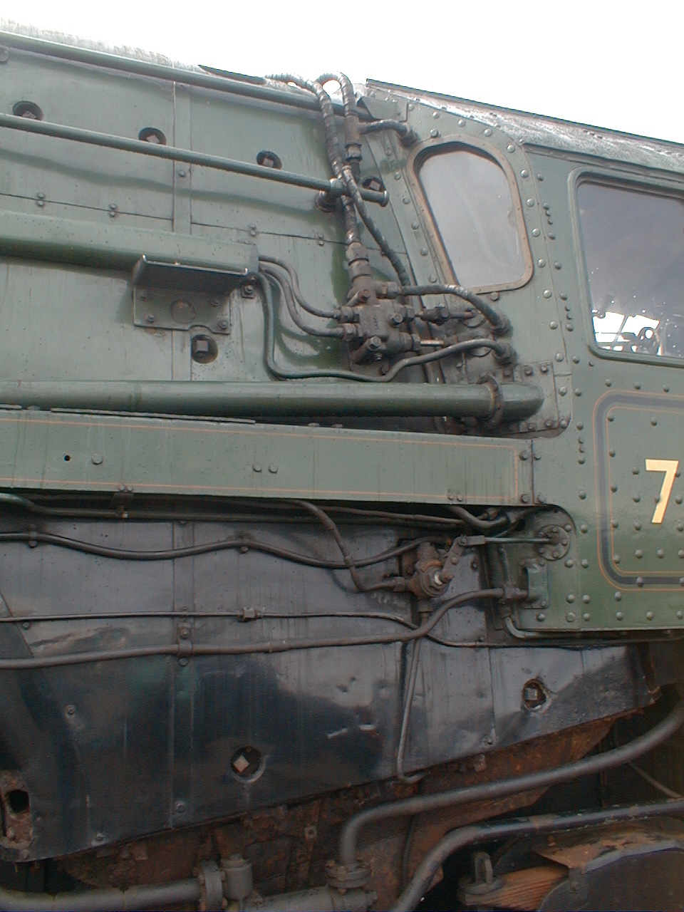
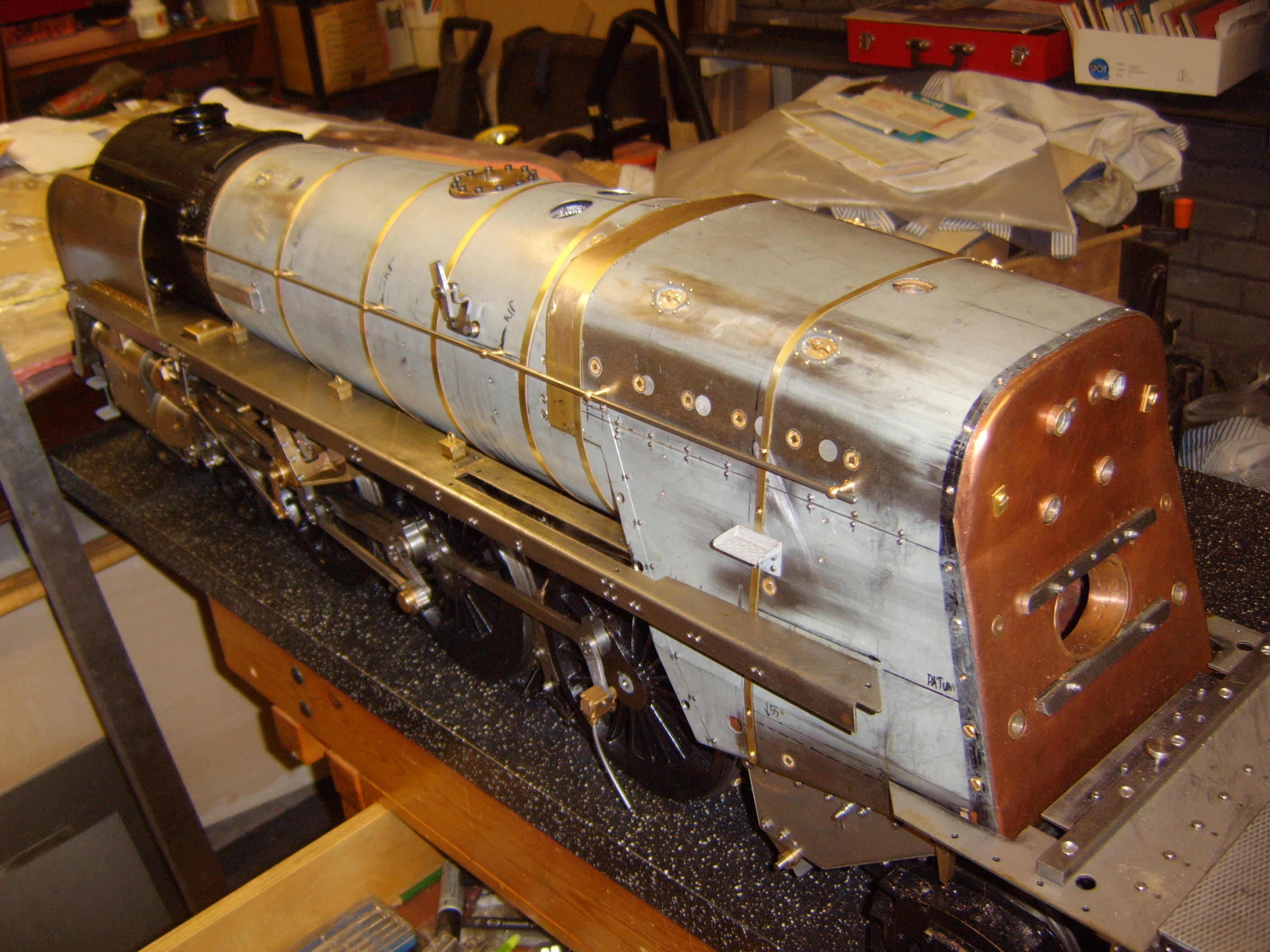
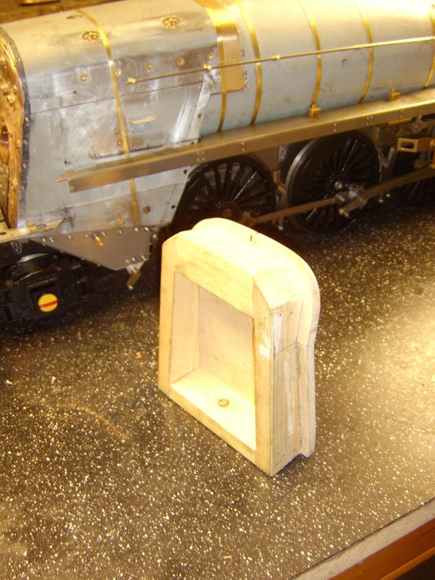
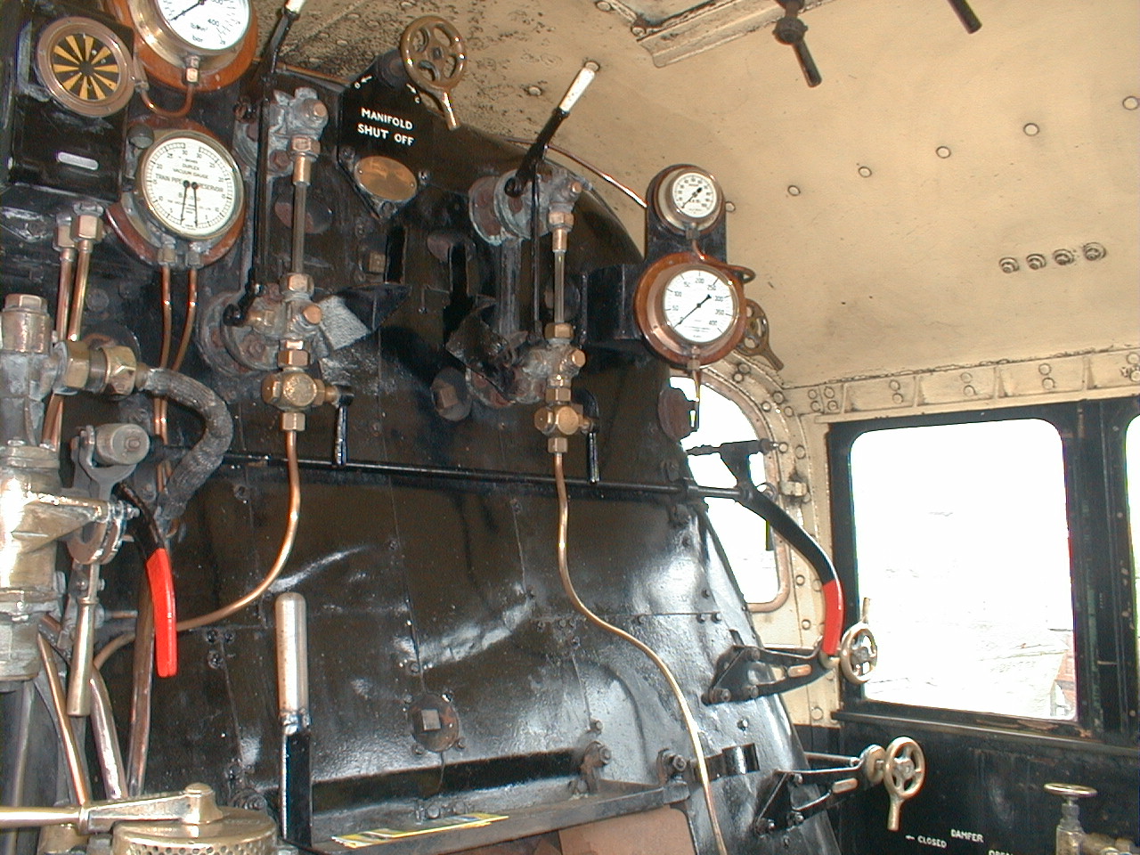
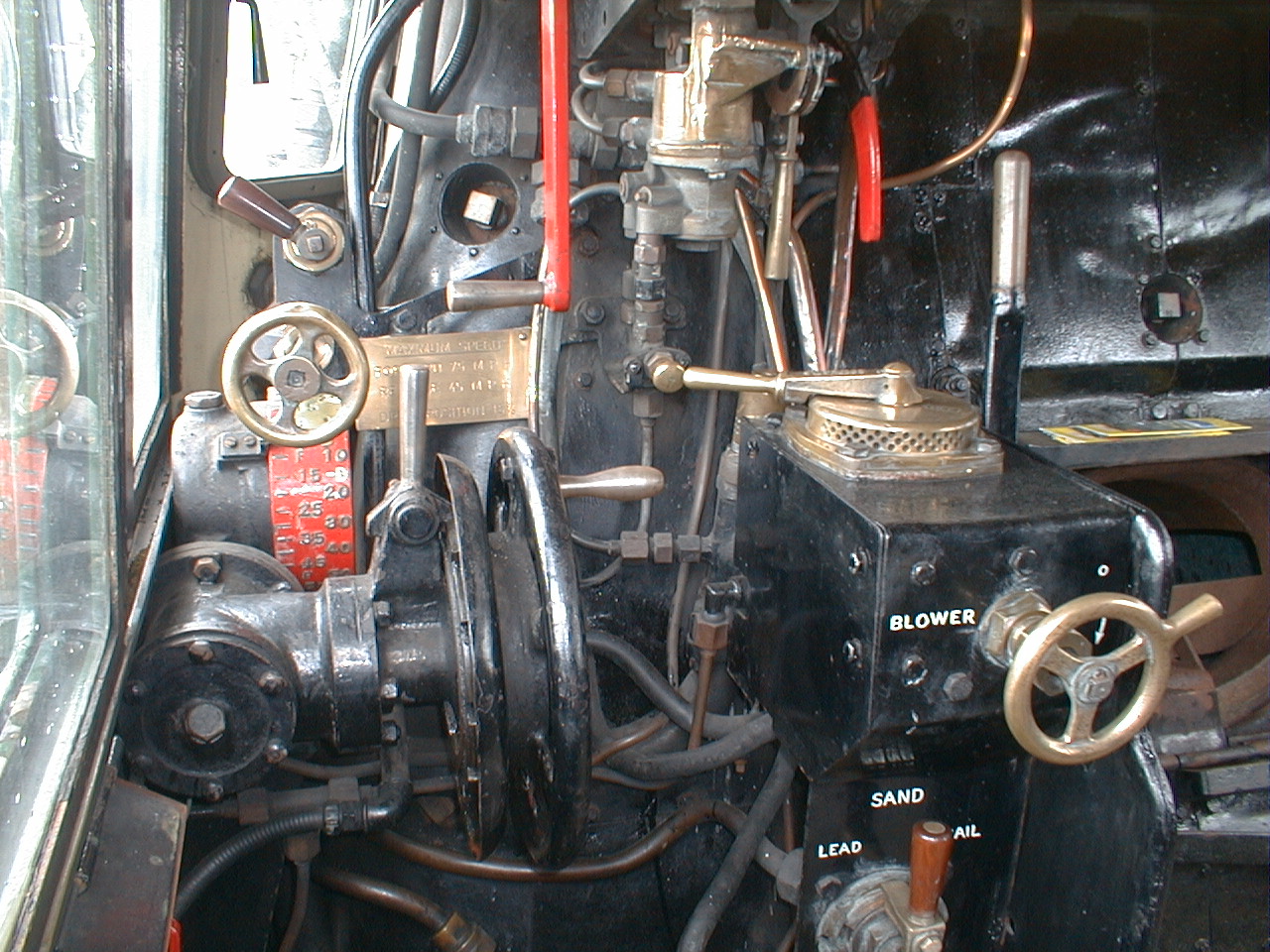
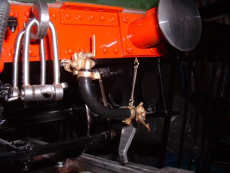
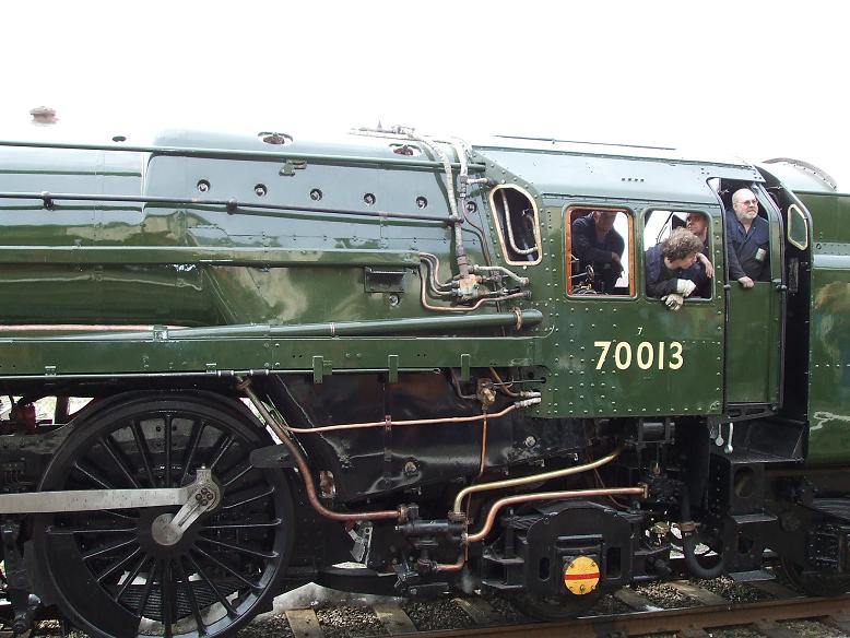