
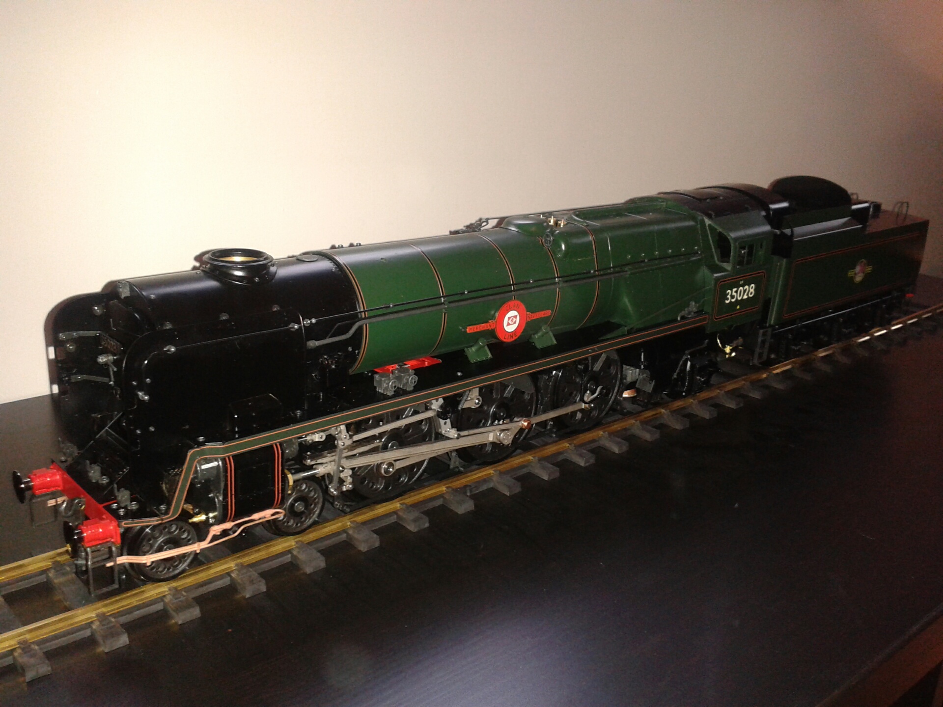
21/11/14 I've decided to build a gauge 1 steam locomotive and I've chosen the recently-released Rebuilt Merchant Navy class 'Clan Line' from Aster UK. These Japanese-made kits seem to have a very good reputation and many successful models have been delivered over the past 40 years or so. The kit arrived today, very well packed and so far I've just browsed through the instruction book which consists of 19 pages of diagrams (but no words). Update 26/11/14: A comprehensive instruction and operating book arrived separately in the post today, along with some extra screws, and all is now a lot clearer!
There is an active G1 group at my North London club at Colney Heath with a large track, and in fact I met another member there yesterday who has also bought the Rebuilt Merchant Navy kit, although he doesn't plan to start building it until next year. I shall start tomorrow!
Step 1 - Cylinders
The model has three cylinders as on the prototype, with three independent sets of Walschaerts valve gear. The valves are slide valves rather than piston valves, so the valve gear is set up for outside admission with the return cranks leading the crankpins and the radius rods attaching to the combination levers below rather than above the valve crossheads. I was initially a bit disappointed because I assumed that the prototype would have inside admission piston valves like the Britannia, with the return cranks trailing the crankpins and radius rods above the crossheads, but on checking this superb drawing I see that it has outside admission piston valves and so the valve motion on the model is spot on!
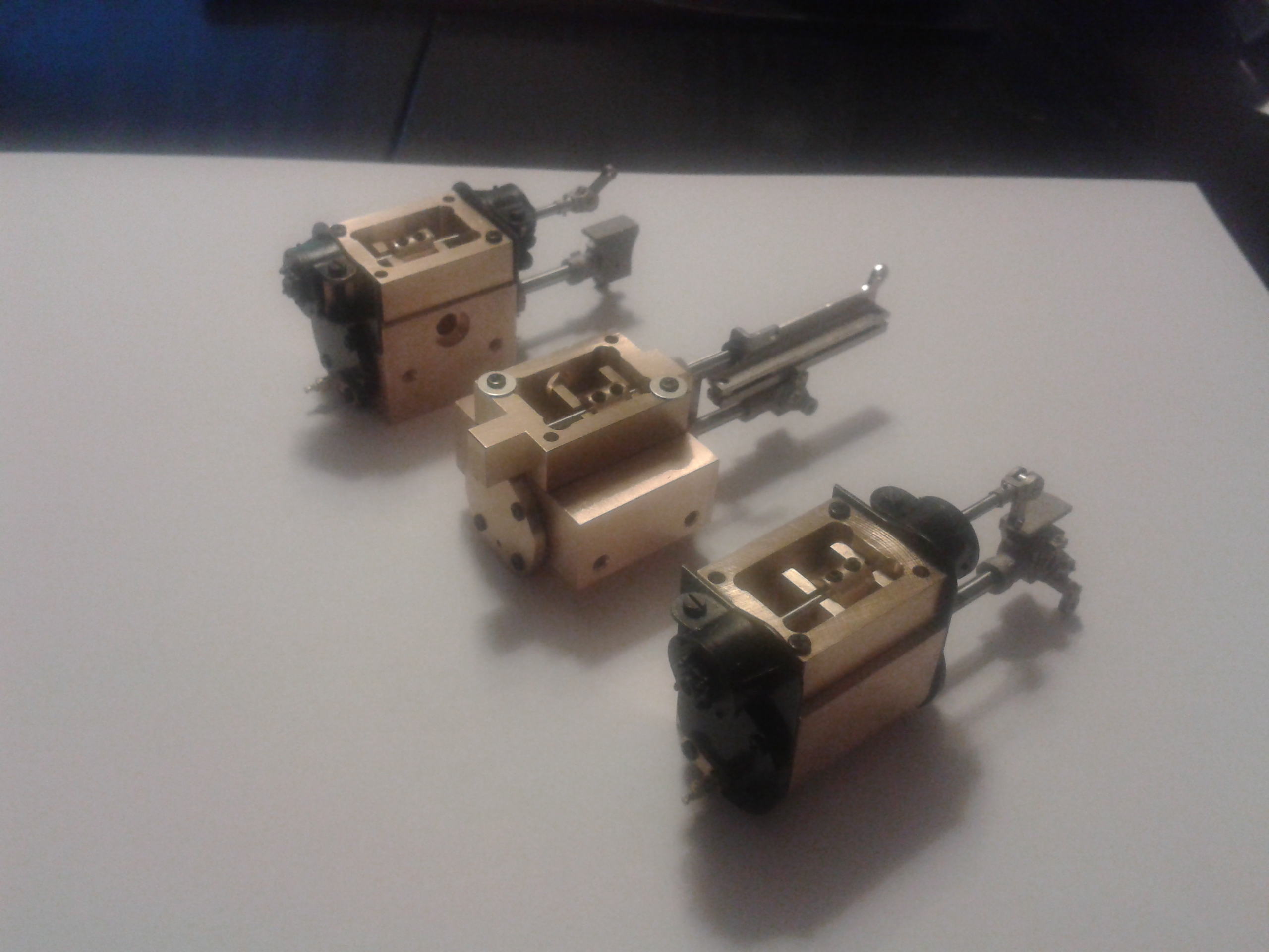 I've now assembled the three cylinders as shown in this photo. The first step was to polish the valve faces by rubbing on a sheet of 1000 emery paper on a flat surface. The parts then went together without too much trouble - one of the front valve cover castings was bent, but I managed to straighten it, and the rear cylinder relief valves needed their spigots shortening to fit in the locating holes in the cylinder covers. The screws holding down the valve chests are slightly too long and need washers fitting, but they will be OK when the covers are fitted later. The fronts of the outside valve chests are about 1mm too short, but this will not be visible when the cylinder cladding is fitted. I used Loctite 222 thread lock on moving parts such as the piston rod to crosshead threads. The drawings indicate that silicone sealant is to be used on the gaskets, and a tube is provided in the kit, but I oiled the gaskets instead following the suggestion in the second page of this excellent article that I found on the Aster USA website. After a bit of polishing of the slide bars on the middle cylinder, all three pistons and valves slide very smoothly.
Step 2 - Main Frames
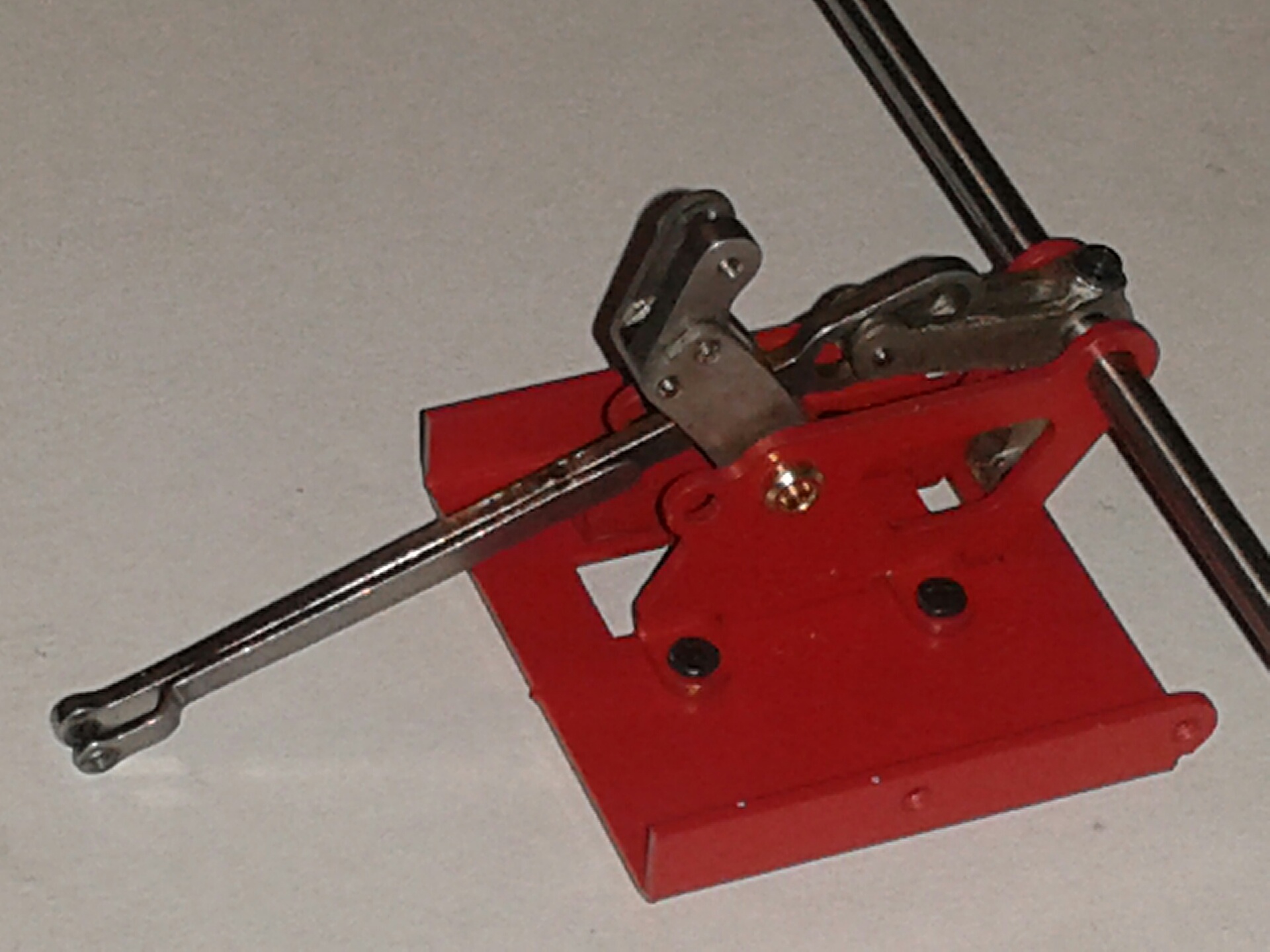 27/11/14 This step involves assembling the main frames with their stretchers, including the middle cylinder, its valve gear and the axle pump with its pipework and bypass valve. The first step is to assemble the radius rod, expansion link and lifting arm into their stretcher, shown (upside down) in this photo. The die block is an excellent fit in the curved slot of the expansion link, but I had to file down the protruding pin connecting the lifting arm to the radius rod to avoid it fouling the trunnion. The lifting arm has a right-angled crank which seems to be superfluous since the reversing rod operates on the left hand outer valve gear, and I had to file the tip of this crank slightly to stop it fouling the stretcher.
 The holes for the pin that links the radius rod and combination lever are too small, and I've ordered a 1.6mm drill to correct this. The instructions which arrived yesterday after I'd ordered the drill say 1.65mm, but the pin is 1.57mm so I expect that 1.6mm will be OK. While I wait for this drill to arrive, I've assembled the axle pump and trial-fitted the frames and stretchers. It all went together nicely and the pipes for the axle pump are perfectly bent to shape.
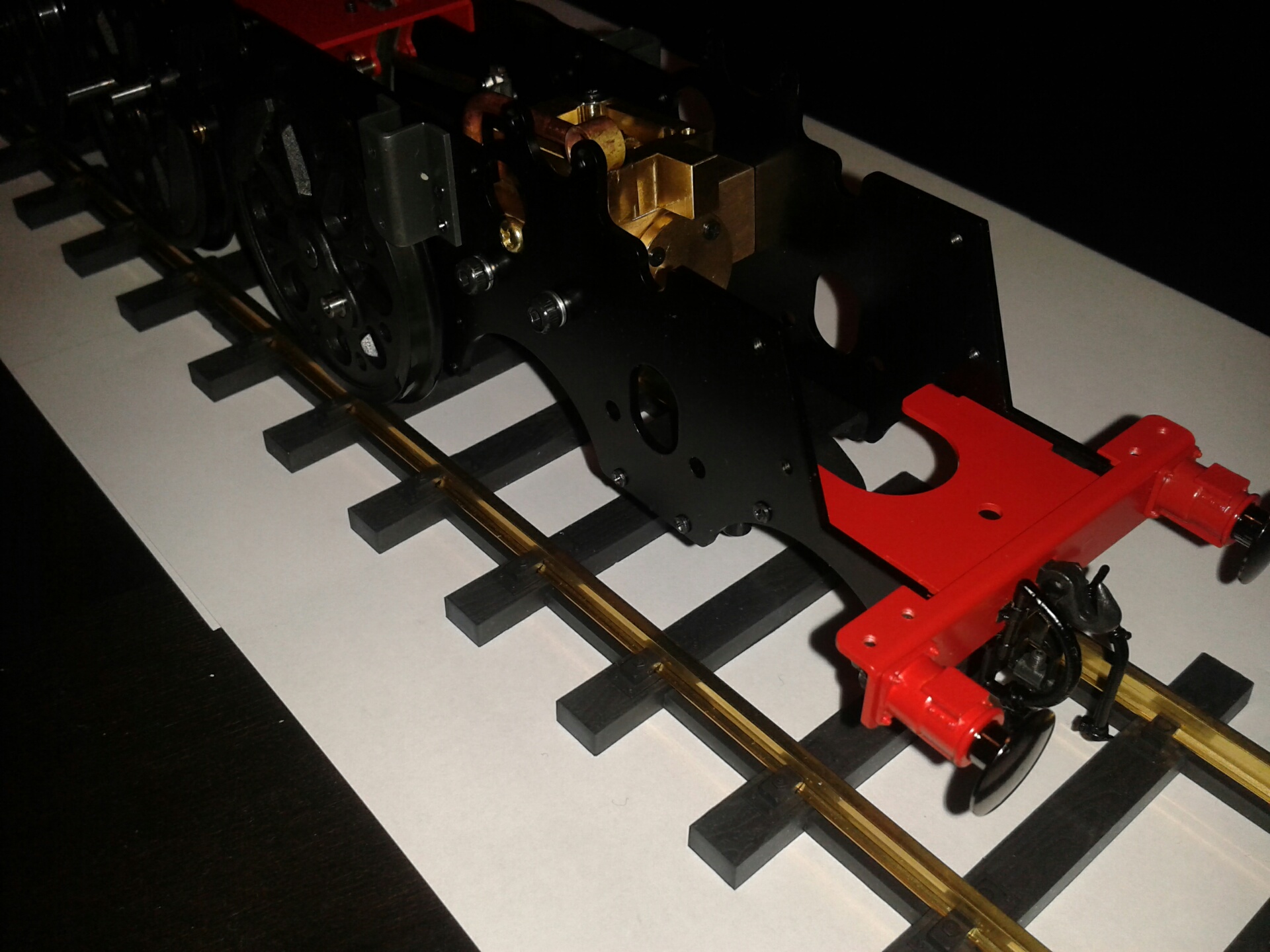
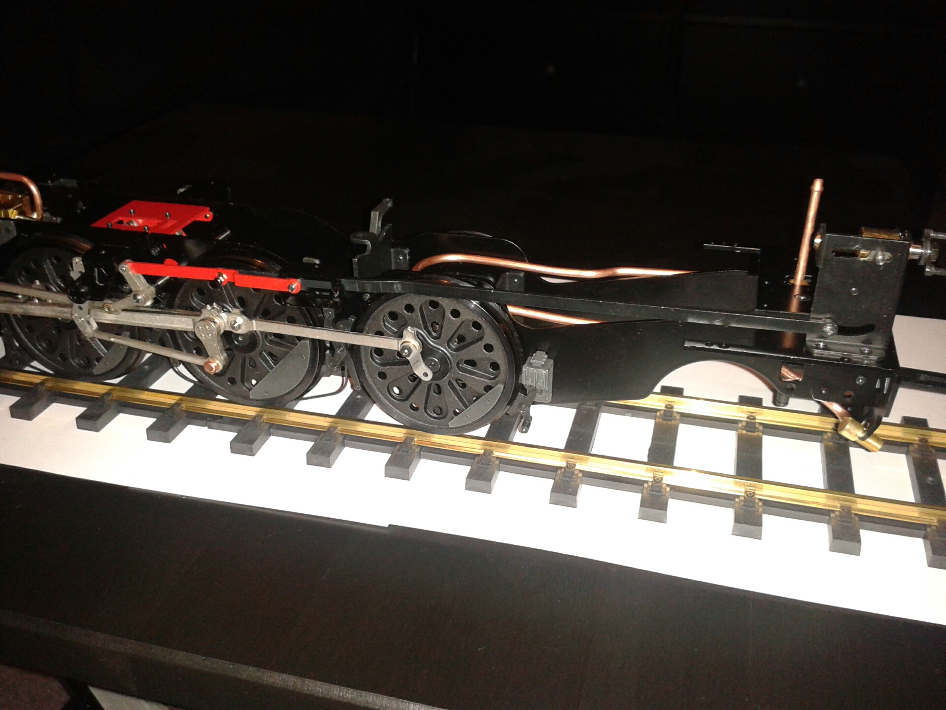
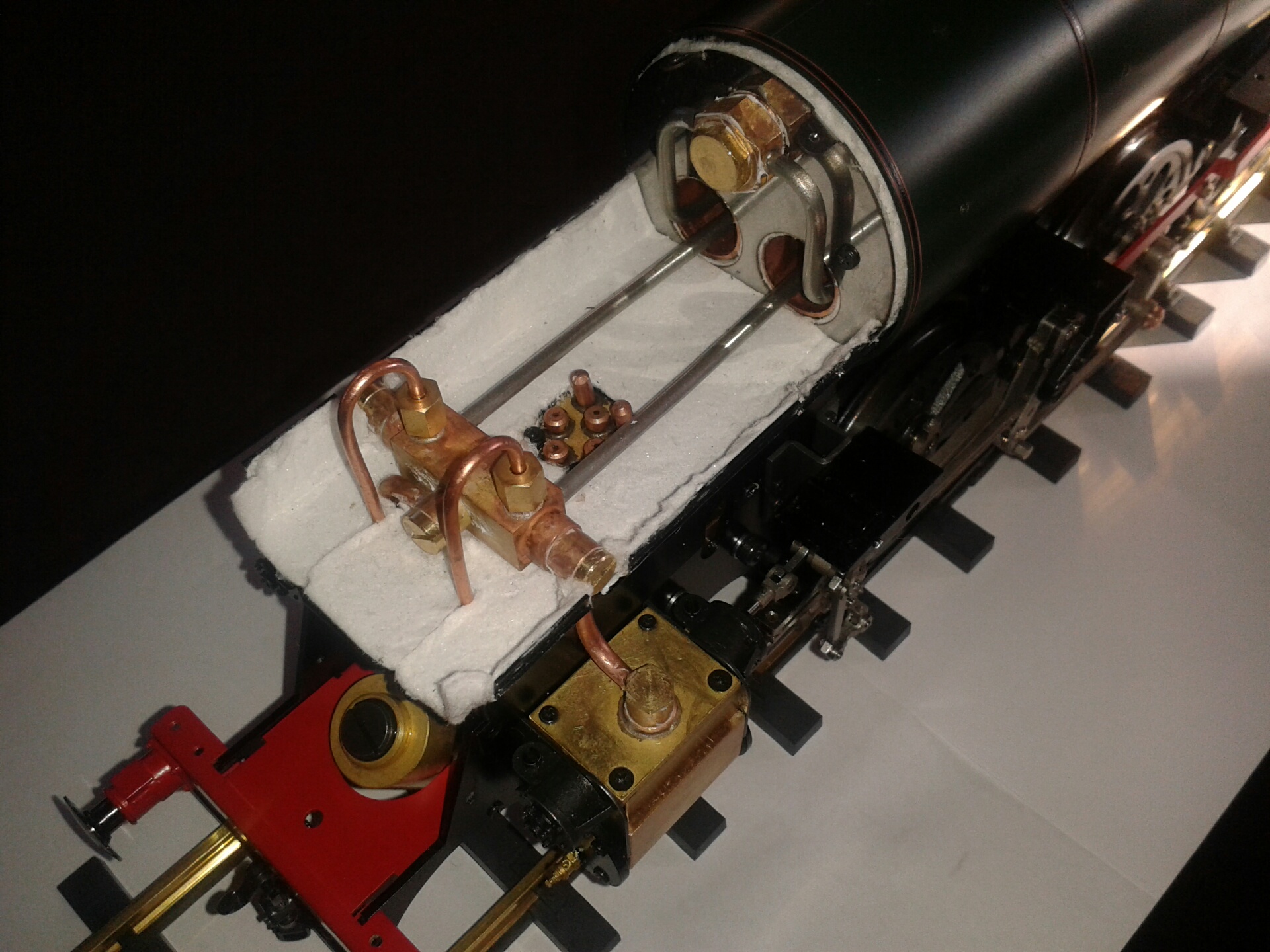
The 1.6mm drill has now arrived and I have completed the frame assembly, checking for squareness on a flat surface and applying silicone sealant to the joints in the axle pump pipework. This photo shows the result - the bypass valve is under the rear stretcher.
Step 3 - Driving Wheels
 This step involves assembling and installing the three sets of driving and coupled wheels along with the rods for the inside piston, inside valve gear and the axle pump, and also fitting the front buffer beam. The axle pump is behind the middle axle but is driven by a crank from the front axle, curving under the middle axle. Each wheel set comes ready assembled to its axle, with the crank pins correctly "quartered" (in fact the outside crankpins are 120 degrees apart since it's a three cylinder engine) and with flats on the main crank pins to locate the return cranks at the correct angle.
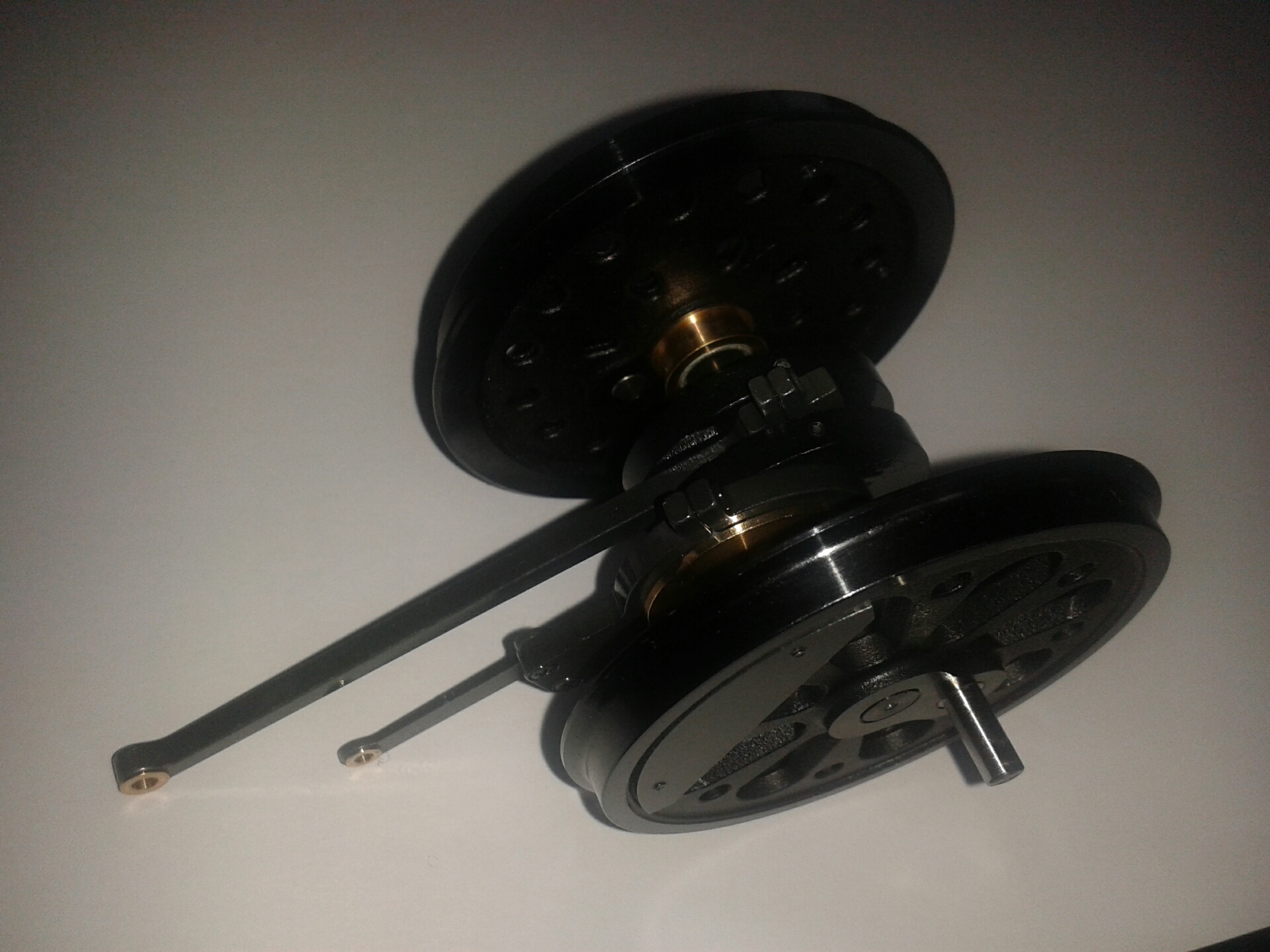
This photo shows the middle axle assembled with its balance weights and the connecting rod and valve eccentric rod. The cranks have PTFE bearings - a split cylinder that springs over the crankpin, and a strip of PTFE to wrap around the large eccentric for the valve rod.
 I have now fitted all three wheel sets to the frames. The front and rear axle boxes slide up and down in their horns with coil springs above the axle boxes, and the middle axle is set at a fixed height. Even with some weight applied so that the springs are fully compressed there is very little weight carried by the middle axle, but I guess that this won't really matter once the coupling rods are fitted. With just the middle axle installed and the crank rods connected up, the chassis rolled very smoothly and the inside valve gear worked correctly. One minor problem was that the eccentric for the axle pump was supplied with the two halves screwed together, presumably so that it could be machined in the factory, and I found that the screws were so tight that I couldn't get them out without damaging the heads. In the end I had to drill the heads off and fit new screws.
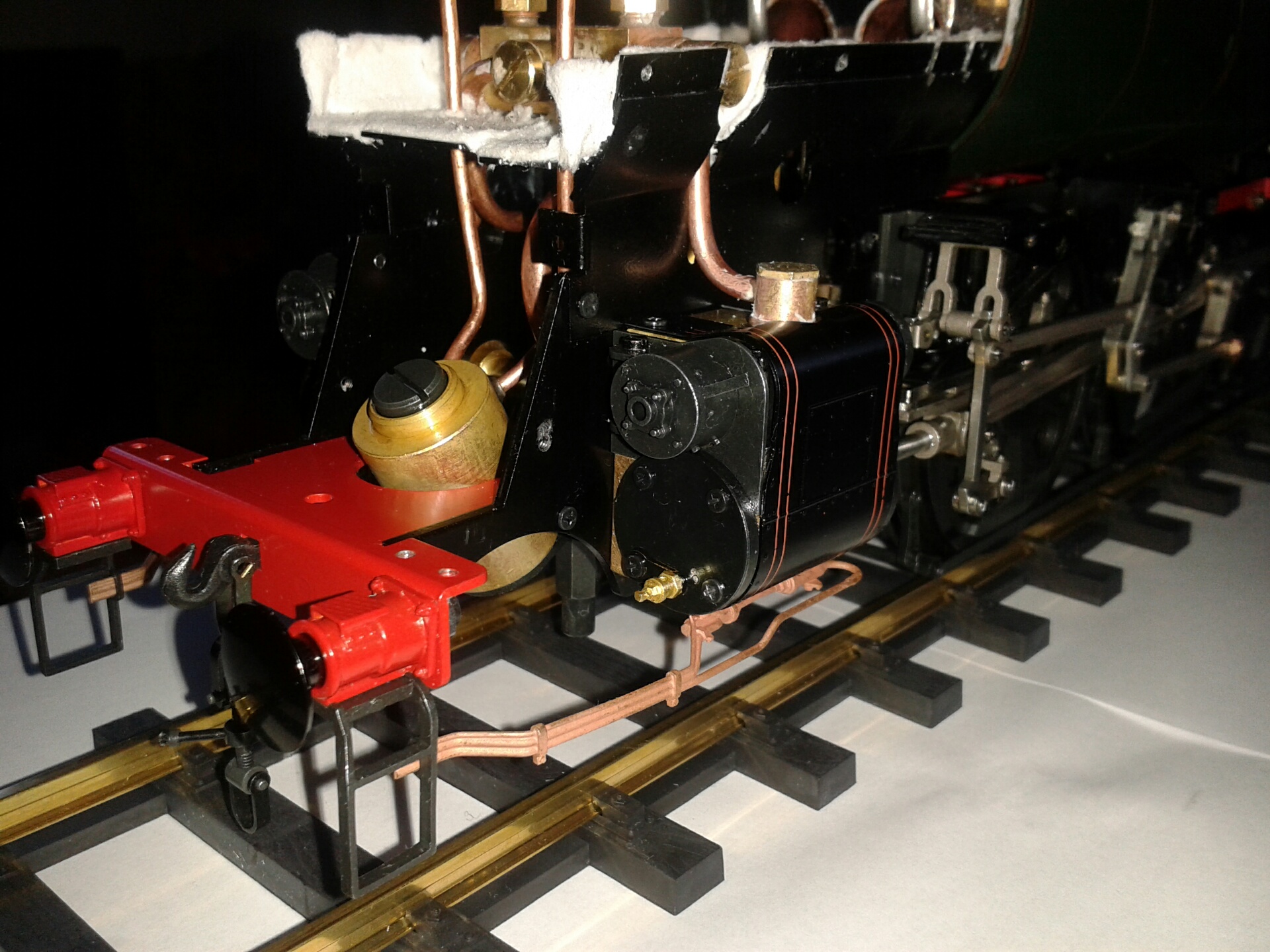
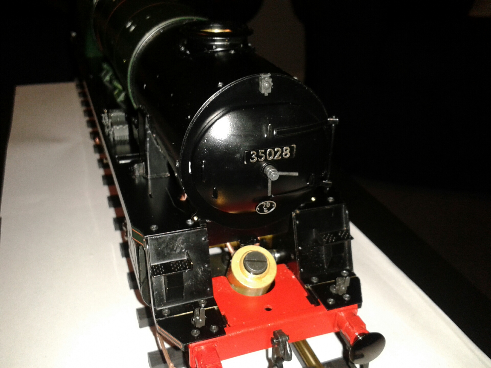
I've assembled and fitted the front buffer beam. The lost wax castings for the buffer stocks and the vacuum and heating hoses are absolutely exquisite, as is the draw hook assembly which has working left and right hand threads. A little bit of filing of the spigots was needed to get the buffer stocks exactly square to the buffer beam. The photo also shows the length of display track included with the kit.
Step 4 - Outside Valve Gear
This step involves fitting the outside cylinders and all the rods and outside valve gear, along with the reverser gear and the brake arms. The first step is to assemble the two expansion links with their radius rods, and I had a little trouble getting these to slide easily even after filing and polishing the inside faces of the outer plates to get the rivetted pins flush. Eventually I realised that the pins on the radius rods were slightly proud of their die blocks and were pressing on the rear plates. After filing these pins down slightly it all worked smoothly.
 Andrew Pullen at Aster UK has pointed me to this forum which includes a thread describing the Merchant Navy build, with contributions from a number of experienced builders. This I'm sure will be very useful. A number of the models seem to have already been completed and steamed successfully. One needs to register on the forum and email the Administrator in order to gain access to the thread.
I then assembled the motion brackets with their swinging links that carry the combination lever and the valve rod link. I had some difficulty screwing the pins into the rear wall of the brackets because the threads seemed somewhat out of true, but eventually I persuaded them to go in. The swinging link needed its inner boss filing down to clear the bracket, as explained in the 'key points' appendix of the instruction book. Incidentally there's a colour version of the key points on the Aster Japan website here - the colour version is needed to make sense of some of the diagrams.
 I then fitted the slide bars and filed and polished the crosshead to give an easy sliding fit, added the union link and screwed the right hand cylinder and motion bracket to the frames as shown in this photo. Miraculously it all slid very smoothly at the first attempt. It seems to me to be much easier to assemble the bracket and cylinder before fitting them to the frames, contrary to the sequence in the instructions. I'll need to dismantle it again to put thread lock on all the pins - I just hope that the other side goes on as easily, because some builders seem to have had trouble getting the slide bars to work smoothly.
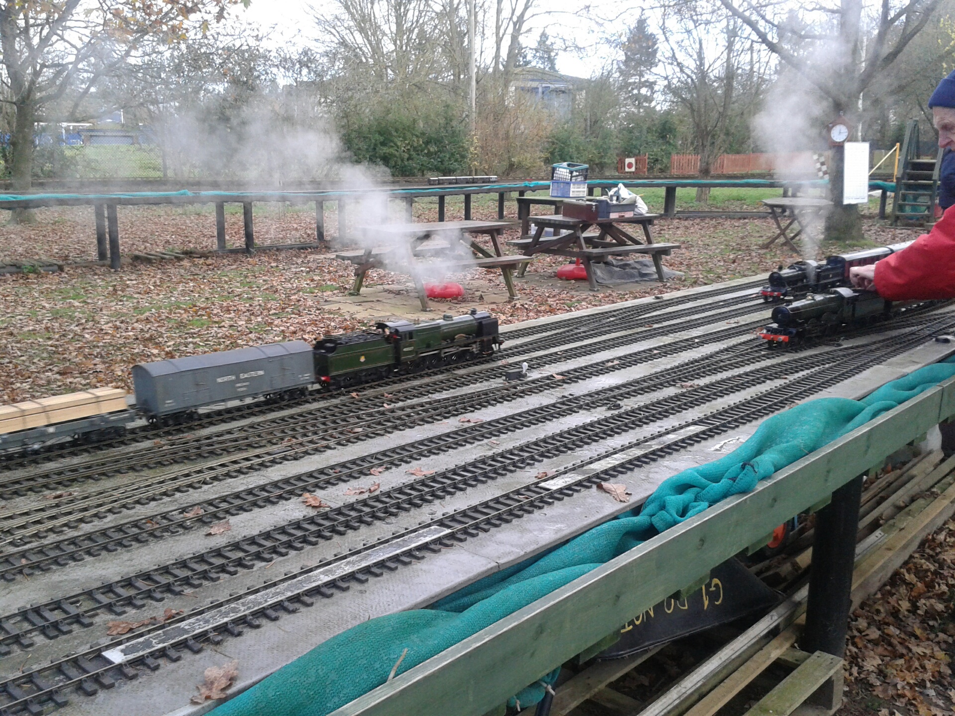
3/12/14 This morning I went down to the NLSME track at Colney Heath, Wednesday being the G1 running day, and it was surprisingly busy for a cold December morning. The photo shows three trains passing. I'll take my boiler along for a hydraulic test in a week or two, before I mount it in the frames.
 I've now completed the right-hand motion as shown in this photo, adding the expansion link bracket, the expansion link, lifting arm, radius rod, return crank and eccentric rod. The lifting arm and its pin needed filing to clear the bracket, but apart from that it all went together without problems and it rolls smoothly. I've also now fitted all the left hand motion apart from the lifting arm. The expansion link bracket needed a little filing to fit snugly in the tapered gap in the rear casting. I fitted the exhaust pipes between the cylinders at the same time as the left hand cylinder, to save undoing it again later.
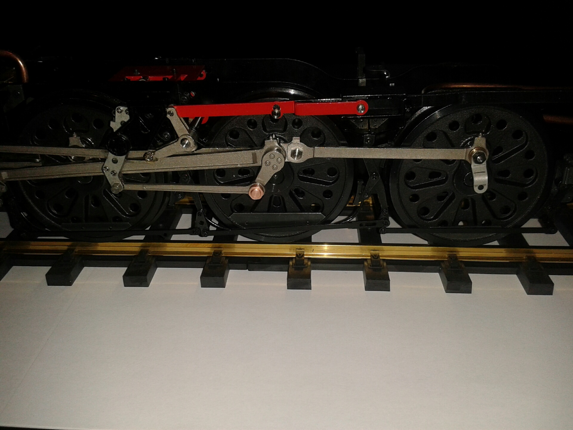
 I've finished the left-hand motion and fitted the reversing gear. Although there's no adjustment in the length of the reach rod, the mid position on the reverser screw and the mid gear on the motion match perfectly, which is a tribute to the overall accuracy of Aster's components. Full movement of the screw doesn't move the radius rods quite to the ends of the expansion link, and the valve inlet ports are not quite completely uncovered in full gear, but I think it's close enough.
I also fitted the brake hangers and the sanding pipes. The kit has one of the sanding pipes behind the rear wheel but this should be in front of the front wheel, as pointed out by one of the contributors to the forum mentioned above. I cut a 3mm length of 4mm tube to act as a spacer on the rear brake pad, and cut the top boss off the front brake hanger to allow me to fit the sanding pipe there. This can just be seen in this photo.
Steps 5 and 6 - Valve Setting
7/12/14 The only adjustments necessary or possible on the valve gear are to line up the three lifting arms so that all three sets of valve gear are in neutral at the same time, and to centralise each of the slide valves on its spindle so that the front and rear ports open by the same amount. The crank on the middle lifting arm, which I thought in step 2 was superfluous, seems to be provided so that the middle and left hand lifting arms can be lined up easily by sliding a 2mm rod (in my case a cocktail stick) through the holes in the frames and this middle crank.
The slide valves are then easily centred by carefully rotating the wheels in forward gear and moving each valve until equal openings are achieved, and checking again in reverse gear. As mentioned above the ports are not quite fully uncovered in full gear either forward or backward, but I hope it will be sufficient. Other builders on the forum seem to have found the same thing. I think that the brass nut on the reversing screw could be made slightly shorter to give a bit more travel on the lifting arms if it proved necessary. Finally I put threadlock on all the remaining screws and pins in the motion gear.
Step 7 - Air Test
 8/12/14 Today I fitted the cylinder covers and steam pipes and temporarily fitted the superheater and oil tank for the air test. Fitting the multiple blastpipe unit was a bit tricky because the exhaust pipe from the outer cylinders needed bending a little to allow the blastpipe unit to sit flat. I temporarily fitted the cover plate from stage 10 to help position the blastpipe, as shown in this photo.
I haven't yet bought a rolling road, but since the middle axle is not sprung I decided simply to secure the chassis at both ends and let the wheels turn freely. This short video shows the model running on air, using my airbrush compressor - fortuitously the rubber hose supplied could be pushed onto the air dryer unit which is the small transparent cylinder that can be seen in the video. The air is already turned on at the start of the video, at a pressure of about 15psi, and as the reverser is wound out from midgear to full forward the engine springs to life. The reverser can then be wound back almost to the neutral position and it continues to run. It runs equally well in reverse. The valve setting is not quite spot on because when turning the wheels by hand in mid-gear one of the valves is admitting air once per revolution. Perhaps I'll take the covers off again and have a look, but I don't think it matters too much.
 The other problem that I noticed was that the PTFE strip on the middle valve gear eccentric had slipped partly out and a piece about 1mm wide and 20mm long had been chopped away by the adjoining crank web. I'll need to request a replacement and try again, perhaps with a dab of sealant on the sheaves to hold it in place.
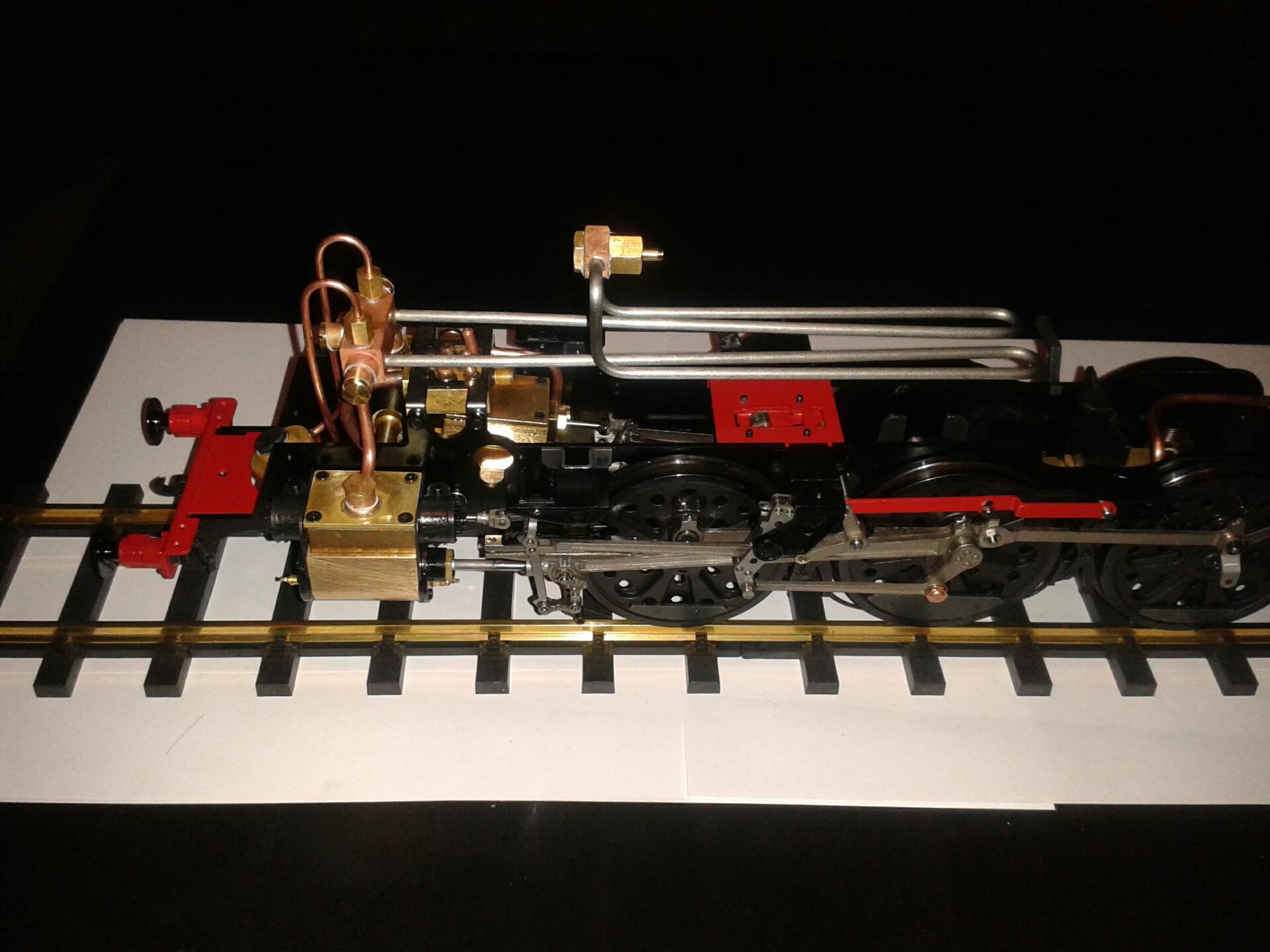
9/12/14 I've fitted the brake rods, as shown in this photo. I also dismantled the middle valve eccentric to inspect the PTFE strip, which is indeed tapered at one end, and I've requested a replacement. I'll need to fit this before I can fit the boiler. I've been advised not to use sealant, but instead to curl the PTFE by pulling it between thumb and forefinger before fitting it.
Step 8 - Boiler Fittings
 10/12/14 I took the bare boiler along to the club at Colney Heath this morning to find out about hydraulic testing. It seems that a twice working pressure hydraulic test is not mandatory for a commercially built boiler, but I decided that I'd like to have one anyway for my own peace of mind. I will fit the water gauge, regulator, blower, feedwater pipe and dome nut, and Norman the boiler tester kindly agreed to modify some of his blanking plugs to cover the three safety valve holes (which are very close together) and the pressure gauge boss. I'll aim to get this test done next Wednesday, weather permitting. Prior to that I'll pump the boiler up to working pressure with the safety valves and pressure gauge fitted to check for any leaking fittings.
This afternoon I loosely assembled the boiler fittings. When fitting the grub screws to the regulator and blower handles I noticed that the larger one on the regulator was black but the smaller M2 one on the blower was silver. On further investigation I found that both black and silver grub screws were provided, the latter labelled SUS, and I'd mistakenly used black rather than silver ones on the slide valve buckles in step 1, and silver ones on the return cranks. I suspect that the SUS ones are stainless and the black ones ordinary steel, so I decided to swap them over rather than risk corrosion in the valve chests. This did give me the opportunity to check the valve setting again and I moved the centre valve very slightly to avoid it cracking open in mid-gear, which I think explains the problem that I noticed during the air test.
11/12/14 Today I lined the firebox with ceramic sheet, which seems to adhere nicely with the white compound, and I fixed the firebox and all the backhead fittings including the water gauge glass and pressure gauge. Tomorrow I'll fit the dome plug and safety valves and try to pump the boiler up to working pressure, using either the airbrush compressor or the tender handpump in my 5" gauge Britannia.
 12/12/14 I connected up the boiler to my 5" Britannia tender as shown in the photograph and pumped water into the boiler until it was full, then closed the regulator and pumped the pressure up. One of the safety valves released at just over 2 bar, then holding this one down the second opened at 3 bar, and the last one opened at 4 bar. The boiler held the 2 bar pressure unchanged for several hours, which I thought was really excellent - the regulator and blower valves and the clack valve must fit perfectly. Then after checking with Andrew at Aster I made up a tool to fit the two small slots in the top of the safety valves and tightened them down slightly to get them all releasing at just under 4 bar. It only took about 1/8th of a turn. I'll do the final adjustment when I first steam, because I know from experience with the Britannia that they can behave slightly differently with steam as opposed to water (perhaps because of the temperature difference?)
Step 16 - Tender Frames
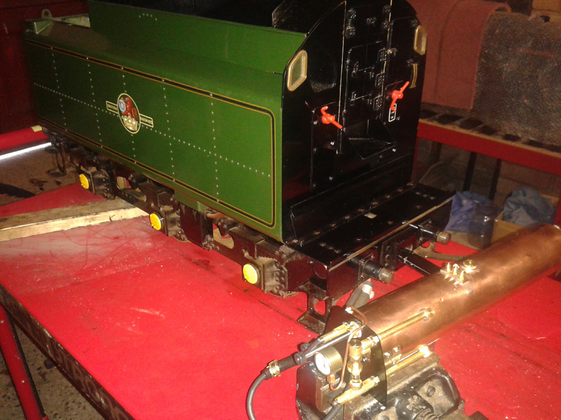
14/12/14 I've decided to work on the tender while waiting to get the boiler hydraulic test at my club. I started by testing the fuel tank for leaks, because I know from the forum that some tanks have had leaks on the top soldered seam and have been replaced by Aster. The tank has a feed pipe with a screw-down needle valve on top, and a filler cap sealed with an O-ring, and an air breather pipe which projects from the underside of the tank and dips into the sump in the tender base which in turn feeds the burners. When the level of fuel in the sump covers the bottom of the breather pipe, the supply of air to the tank is cut off and the fuel therefore stops dripping from the valve into the sump. Thus a constant level of fuel is maintained in the sump, giving a constant fuel supply to the burners irrespective of the level in the fuel tank. This all depends on the tank being completely airtight. Incidentally the PN3-1.9 neoprene O-ring shown on the plans is too big to fit into the top of the feed valve tube, but there was also a PS3-1.9 silicone O-ring in my kit, the same size but softer, which works perfectly.
 Having fitted the valve I half filled the tank (using white spirit, since I didn't have any meths), fitted the filler cap tightly and opened the valve a turn, so that a steady stream of fuel ran out. I then placed my finger firmly over the breather, but this did not stop the flow completely - there was a drip about once every 3 seconds. So I assumed that I had a faulty tank that would need to be returned, but I decided to locate the leak by immersing the empty tank completely in a bucket of water and blowing hard into a tube attached to the breather pipe, as if looking for a puncture in a bicycle tyre. Surprisingly there was not the slightest bubble.
Thinking more about this, I realised that the fact that I was holding the tank in my hand to test it was probably warming the contents sufficiently to expand them so that drips were released. I tested this by blocking the breather pipe with a rubber hose with a closed end and placing the tank on the workbench, and sure enough there was no drip. Moreover when I placed my hand on the side of the tank it started to drip within a couple of seconds, and stopped equally promptly when I let go. A hand on either side of the tank gave twice the rate of heating and hence twice the drip rate! This was all done in a cold garage with cold liquid, so the effect may have been more pronounced. So perhaps some of those tanks returned to Aster were not faulty after all?
15/12/14 I assembled the hand pump and fitted the pump, water tank and fuel sump into the baseplate and the baseplate to the frames. No problems here, although the links to the pump handle flop from side to side a bit and would be better with a couple of washers under the nuts. I also fitted the pipe brackets 18-8 to the underside of the baseplate - they need M1.7-4 screws rather than the M1.4-4 in the drawing. I suspect that either the sump or the baseplate will need to come off again in order to fit the front axle.
Step 17 - Tender Wheels and Body
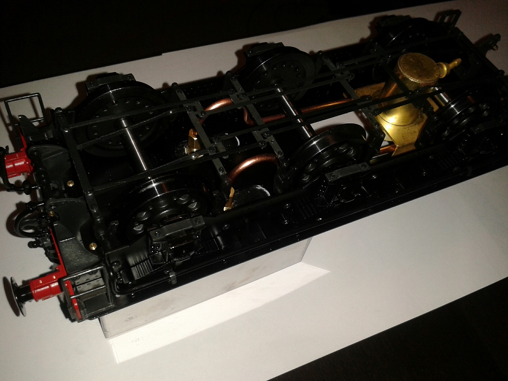
 16/12/14 I fitted the wheels and springs. The best sequence of assembly seems to be to fit the water tank, pump, internal pipes and sump to the baseplate along with the pipe brackets 18-8, then fit the dummy springs to the frames, then the wheels, axleboxes and horn keeps, then fit the baseplate to the frames, then fit the two pipes under the baseplate, passing them through the sump bracket. The sequence described in the instructions doesn't really work. I filled the tank with water and checked that the pump worked and that there were no leaks.
I then fitted the folding cab doors to the front of the tender body, along with the handbrake and coal plate. The cab doors each have three hinged sections and are each fixed to a bracket behind the front flange of the tender body. The brackets are a couple of mm too long for the door pillar and the top bracket is threaded M1.2 rather than the M1.4 shown on the drawings. To solve this I drilled the top brackets out to 1.2 mm and fitted a 12BA screw with a nut underneath the bracket to serve as the top pin for the door pillar.
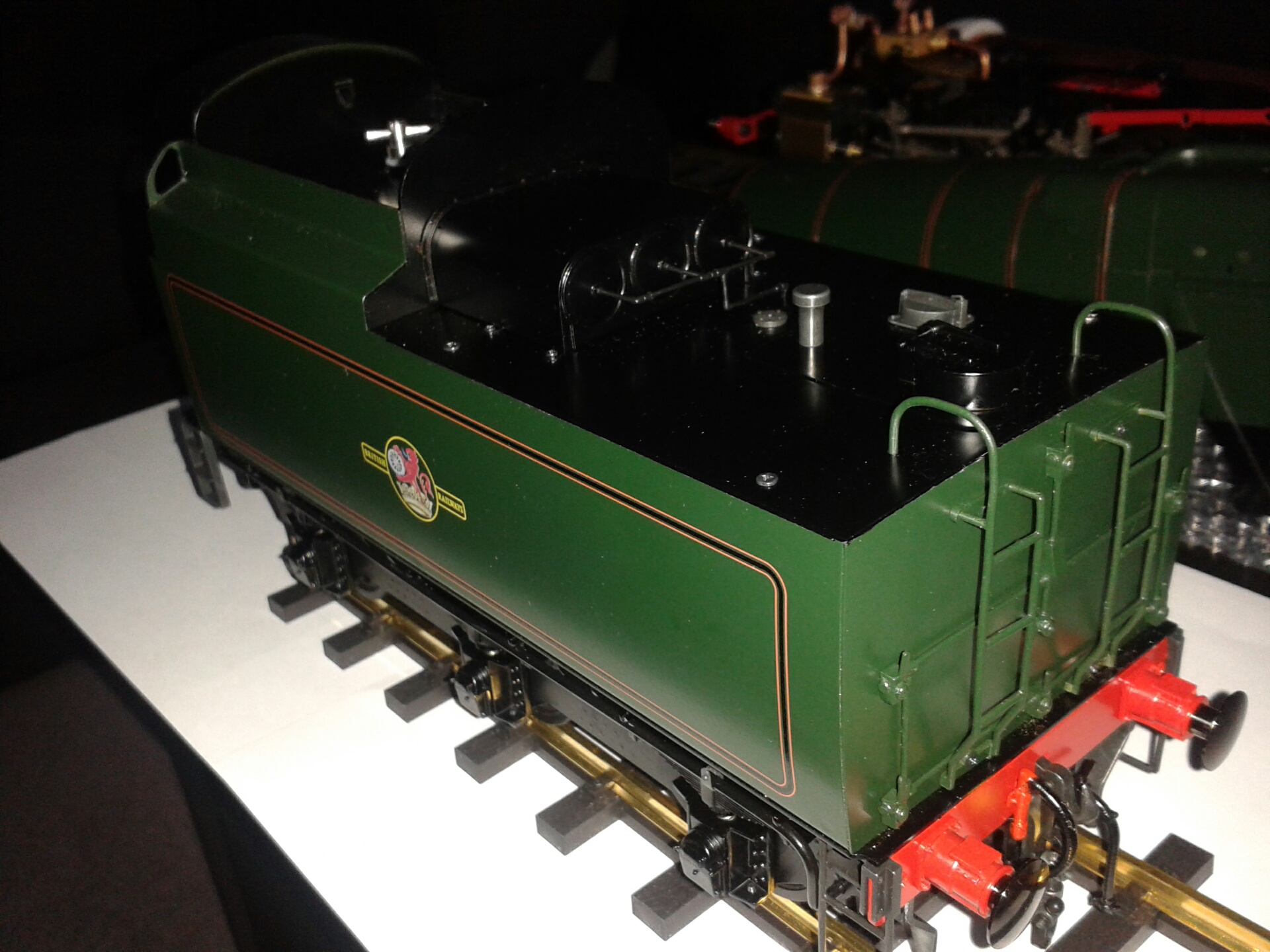
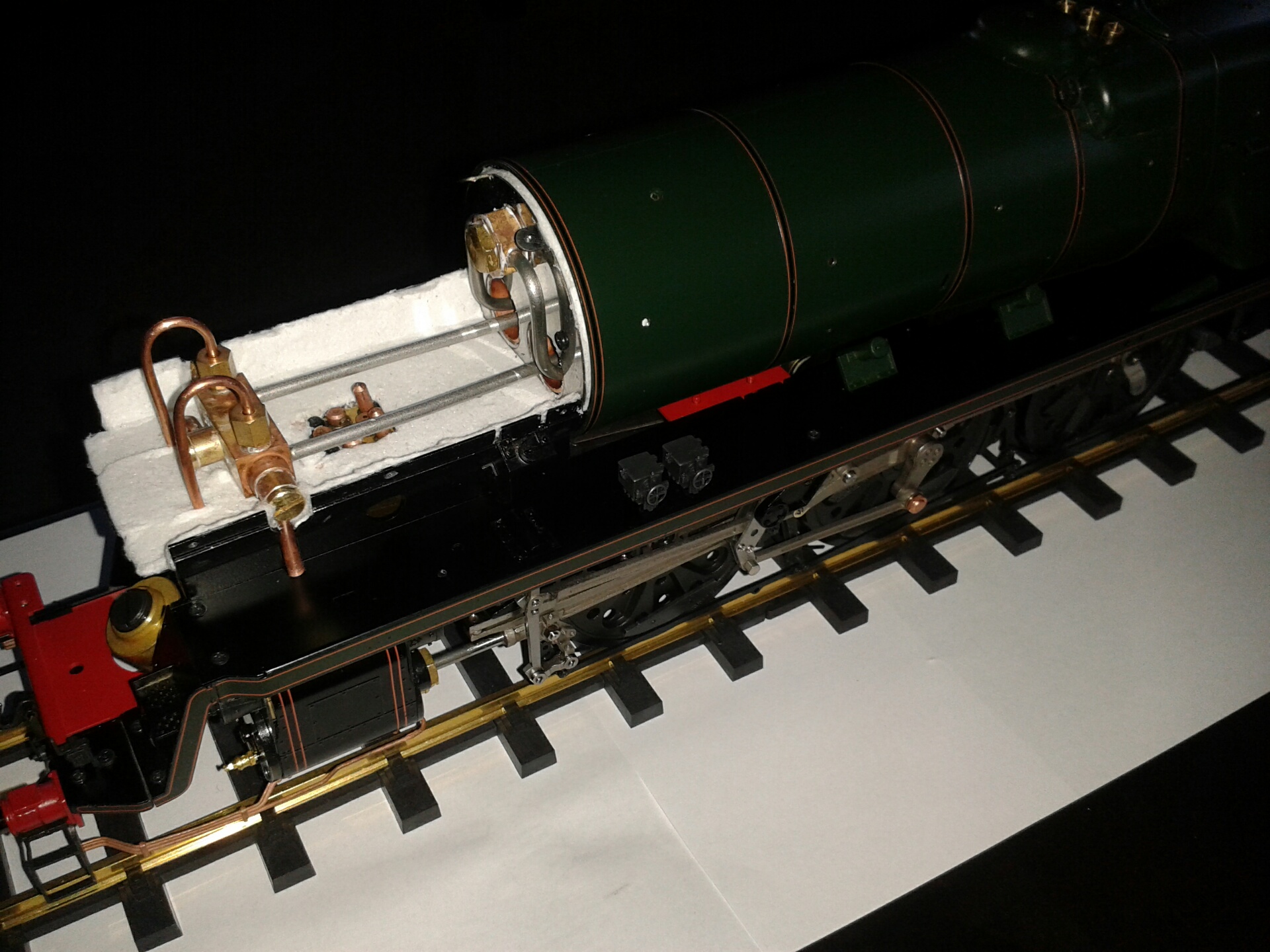
I've temporarily attached the body to the baseplate for the photograph, but I'll take it off again to fit the rather elaborate (but sadly almost invisible) braking system which is the next step - it reduces the risk of damaging the beautiful green paintwork. The photo also shows the superb level of detail on the frames and the spring castings.
Step 18 - Tender Brakes and Top
 17/12/14 This morning I took my boiler to the club at Colney Heath and had a hydraulic test to 8 bar or 120psi, twice working pressure, with no problems. We also checked the pressure gauge against the test gauge - it was underreading slightly at 1-2 bar and overreading slightly at 5-6 bar, but pretty much spot on at the working pressure of 4 bar.
This afternoon I fitted the tender rear buffer beam and all the brake gear, as shown in the photo. The links 18-11 and 18-24 on the front and rear trunnions are tapped M1.2 rather than M1.4, and an M1.2 screw has too small a head to retain the brake rod. I drilled these links out to 1.2mm clearance and used 12BA screws and nuts to hold the rods. I used M2-2.5 rather than M2-4 screws to hold the front steps; the M2-4 screws project too far above the baseplate. Only time will tell whether I have enough M2-2.5 screws for subsequent steps. I omitted the 1mm rods under the tender sides - these cannot be fitted because the body support brackets have not been drilled to receive them. They would in any case be hardly visible.
 18/12/14 I've bought some 6BA brass washers and fitted two of these under the nuts on the pin securing the hand pump linkage to the pump body (see 15/12 above), and this stops the pump handle from flopping from side to side. I then fitted the tender top with its vacuum cylinders and pipes, and the lighting pipes and ladders on the rear of the tender. I used tiny dabs of Araldite applied with a toothpick on the inside of the vacuum cylinders to fix the pipework, and the same for the top joints of the handrails on the front of the tender - I left the bottom joints unglued in case I ever need to remove the tender body from the baseplate again. The delicate pipework casting on the rear of the tender does not sit quite flat because the holes are slightly too far apart, so I've ordered a set of clockmaker's broaches to elongate the holes. I suspect that the broaches will also come in handy for the loco bodywork, from what I've seen on the forum. Apart from this and a few dabs of paint on the screws that I've replaced, this completes the tender, and very nice it looks too.
20/12/14 The broaches arrived and I used them to correct the holes for the pipework casting, and fitted this with a tiny dab of Araldite in each hole. I've noticed that the prototype doesn't have the vertical pipe between the lamps on the right hand side, but it's too late to correct this now. I painted the 12BA screws and I also put red paint on the two rather prominent screws on the buffer beam, and painted the standpipe of the vacuum hose red.
Step 9 - Boiler Casing
21/12/14 I'm now resuming work on the loco. The next steps involve fitting the boiler casing to the boiler, fitting these to the frames, and fitting the smokebox. I've been doing some trial fitting of the boiler and its case to the frames, and trial assembly of the smokebox components. I've fixed three 10mm wide layers of the ceramic insulation around the front of the boiler to centralise it in the casing, as recommended in the updated instructions. I've also filled four superfluous holes in the corners of the smokebox saddle, using epoxy and a dab of paint.
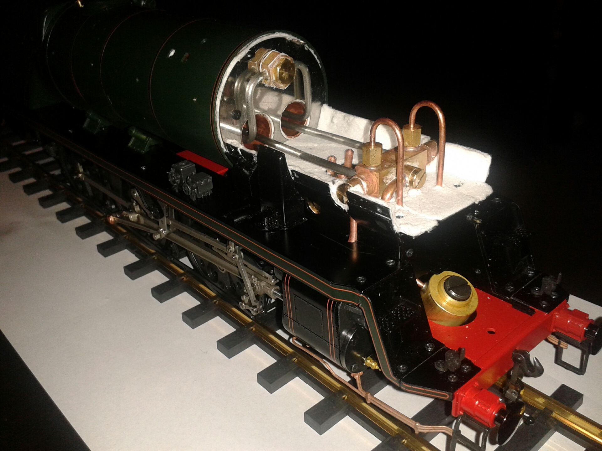
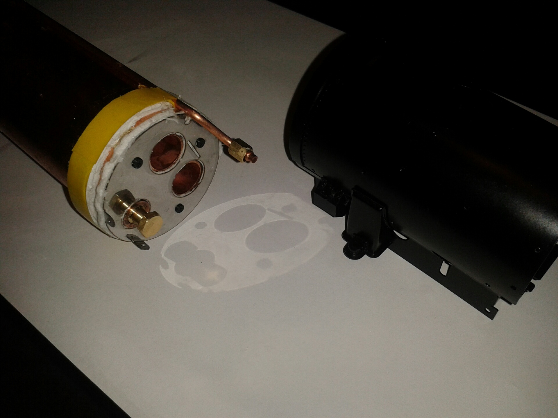 22/12/14 The replacement PTFE strip for the middle valve eccentric arrived today (see 8/12 above) and I fitted this, checking carefully that it was seated squarely all round. The photo shows the boiler front end with the blower pipe and insulated cover plate fitted, and the three layers of insulation around the barrel protected by a strip of tape. The smokebox is also shown, with the sandbox and air cylinder cover castings fettled to hook into the slots between the upper and lower halves. I also painted the area around the safety valves matt black, to avoid the bare copper showing through the hole in the boiler casing.
 24/12/14 I've added the pipework castings to the boiler casing. These went on quite easily with just a little bit of filing of the hooks that engage with slots in the casing. I also checked that the holes for the handrail stanchions were clear, by running an M2 screw through them - it would be a nuisance to have problems fitting these after the boiler is fixed. I then fitted the boiler into the casing. I found that the three layers of ceramic insulation around the front of the boiler were too thick to fit through the middle of the boiler - the boiler case is narrower at the rear end of the front parallel section because there is an internal flanged joint, so I had to remove one layer. Perhaps I had used more sealant than the authors of the instructions.
When fitting the boiler to the frames the firebox casing has to fit around the water pipes, but I found that this went together quite easily - the trick is to completely unscrew the rear stretcher and the water bypass bracket, and fit just the top centre screw out of the five holding the backhead to the casing. The nut on the vertical water pipe can be taped up out of the way near the top of the pipe. The bottom sections of the firebox casing can then be sprung apart slightly to fit over the water pipes, with the cab floor hooked over the vertical water pipe and tipped downwards at 45 degrees at the front to stay clear of the casing as it is eased down. The photo shows the result, and I must say that the level of detail on the boiler casing is absolutely exquisite, with all the panel joints and rivets picked out and all the washout plugs and mudhole doors represented.
There'll be a short interlude now for Christmas, with waves of grandchildren visiting. Happy Christmas to all.
Step 10 - Steam Pipes
 28/12/14 I've fitted the smokebox saddle, steam pipes and lubricator as shown in the photo - they all went together without any problems - just a little jiggling needed to get the tongue on the saddle engaged in the slot in the boiler front plate. I filled the lubricator with oil and blew oil through the pipes before fitting it, which will hopefully help to get it started the first time I steam. I know that displacement lubricators work by having steam travel in to the oil container and condense there, with the resulting water sinking to the bottom and displacing the oil out of the pipes, but I don't entirely understand how the same pair of pipes serve to let steam travel one way and oil the other. Anyway, by all accounts they seem to work. I was given a rolling road and steam raising fan for Christmas, so I'm pretty well set up for steaming now. I had a visit yesterday from Garth, who lives fairly close by and is also building the Aster RMN - he already has three other Asters! He's at about the same stage as me and it will be nice to see the two engines steaming together. He very kindly dropped off a replacement part from Andrew at Aster, which will enable me to continue without delay.
Step 11 - Running Boards
 The first step here is to fit the cylinder covers and drain cock pipework, which are all incredibly finely detailed. I noticed that the cylinder covers are narrower towards the top and leave a little of the brass cylinder visible, so I painted this area of the brass in matt black before fitting the covers. This is not a criticism of the kit because the prototype has the same feature, but I don't know why. I also painted the lugs on the cylinder pressure relief valves. The front ends of the drain pipes are secured by loops behind the front steps, which are fixed to the underside of the buffer stocks.
 29/12/14 I've fitted the left hand running board. This involved a bit of filing to get a good fit, as described in the key points document - this colour version shows in red the areas that need to be filed. I took a little off the inner edge of the running board where it touches the saddle, and quite a lot off the joint between the two front parts to enable the rising section to sit snugly against the frames and to line up the screw on its underside that attaches it to the frame.
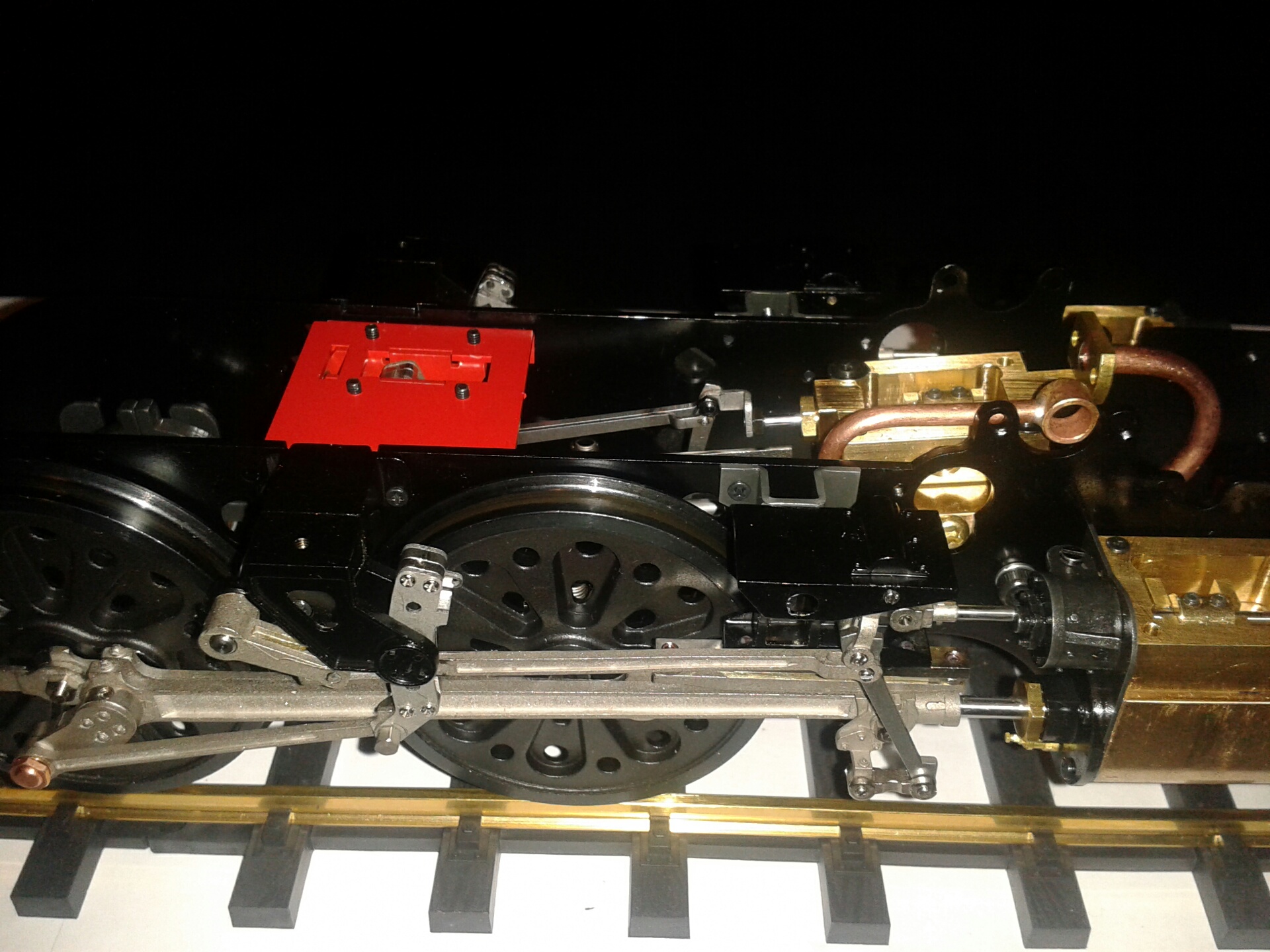
The rear of the two sand box fillers needs to be moved outwards by 3mm to clear the boiler casing. I made a little jig to drill the new holes, by drilling two 1.6mm holes 3mm apart in a strip of steel and bolting this through each of the existing holes in turn. I debated whether to move the front filler out to match, but it has a longer pipe than the rear filler and so this doesn't look quite right - I left it as it was, and I think this looks better. The screws protruding from the red plate holding the inside valve gear are still visible with the running board in place. It would have been better to use M2-2.5 screws here and I considered trying to change them but didn't want to risk disturbing the valve gear at this stage. I settled instead for painting the screw ends red - they can be seen in this photo.
 The screw hole in the running board near the rear filler is nowhere near the threaded hole in the bracket, and I decided to fill the hole with epoxy and not drill a new hole - the running board seems perfectly solid without it, and no screw is shown in the instruction diagram. The front sandbox casting needs to be hooked onto its slots in the saddle as the running board is fitted - it can't be fitted once the running board is in place, other than by cutting off the bottom end that engages with the running board.
30/12/14 I fitted the right hand running board, with the same repositioning of the rear sand box filler and filing of the plates to fit. Note that the larger of the two lubricators should be behind the smaller, not as shown on the instruction diagram. One minor criticism is that some of the castings, such as these lubricators and some of the fittings on the tender top, are finished in a dull grey colour (some sort of chemical blackening process, I think) while others are painted in the same satin black as the frames and smokebox. I'm tempted to airbrush these castings to a matching finish. The larger casting attaching to the right hand side of the smokebox - some sort of air reservoir cover, I believe - needed its bottom peg cutting off and a small amount filing off the bottom of the casting to allow it to sit snugly on the running board. The peg doesn't match the position of the hole in the running board, and it doesn't really seem to be needed as the casting will be held securely once the smokebox top is fitted. I also fitted the front plate between the frames, with only very minor filing to fit. Apart from fitting the name plates, which I'll leave until later, this completes step 11.
Step 12 - Smokebox
 31/12/14 Today was mainly spent taking the grandchildren to Whipsnade, but I managed half an hour on the smokebox this evening. I filed a small bevel on the rear edge as suggested in the forum, and the smokebox then slid into the boiler cladding with no problem at all - I didn't have to tap it in with a hammer and piece of wood as others seem to have needed to do. All the screws around the smokebox went in without any problems, given that I had earlier elongated the bottom holes in the front edge. Tomorrow I'll dismantle it again to fit the insulation, chimney and smokebox door.
1/1/15 I rubbed down the smokebox number plate and shed plate to reveal the lettering, which looks very nice. I just need to touch in the ends of the number plate where the paint has been rubbed off, and I might perhaps try painting the exposed metal in white at a later stage. I then added the chimney and petticoat pipe and other fittings and insulation to the smokebox and the door, and refitted the smokebox and tightened up the screws at the rear of the boiler and the one underneath. I'm very impressed with the way it all fits together.
Step 13 - Fittings - Left Side
 2/1/15 Today I fitted the left hand smoke deflector, hand rails and steam pipes, and the speedometer. The smoke deflector needed a bit of filing of the tongue that fits into the running board and also the rear edge of the bottom front section that abuts the steps. Note that the long brackets on the top of the smoke deflectors are left and right handed and are packed incorrectly - the one for the left is in kit 14 and the right is in kit 13. I found that the front handrail stanchion on the smokebox was not quite in line with the ones on the boiler cladding - it was about 1-2mm too low. The handrail can easily be flexed down to fit through it, but I find wonky handrails a bit annoying. The root of the problem seems to be that my smokebox saddle is slightly raised at the rear end, just by 1-2mm, and this also lifts the front of the boiler and cladding. I tried loosening the four screws that hold the saddle to the frames and pressing the rear end down, and this seems to have helped a little bit. To improve the alignment further I'd need to elongate the hole for the stanchion and fit a nut on the inside - I'll wait to see how the other side works out before deciding.
The 1mm and 2mm pipes along the side of the boiler were cut and bent to shape and held in place by two brackets with tiny M1.2-2 screws. The three 1mm rods supplied in the kit are not sufficient for this pipe and the boiler and smoke deflector handrails, not to mention the 1mm pipes on the tender which I don't intend to fit, so I'll need to request a bit more from Aster for the second smoke deflector. The speedometer casting is screwed under the running board and the end of the cable hooks into the crank on the rear coupled wheel.
 3/1/15 Today I moved on to the rear end of the left hand side. I fitted the front and rear damper doors to the ashpan, along with their operating linkages. This is all extraordinarily detailed but also very delicate and quite fiddly to assemble. The linkages do work, although I'm tempted to superglue the joints to avoid parts being knocked off at the track. The panel above the front damper door, part 13-28, has the lug for the operating spindle offset slightly to the outer edge whereas it should be offset to the inner edge, so I had to bend a dog-leg into it to accommodate the spindle. Both parts 28 are the same and so the right hand side should work without this treatment. I trimmed the projecting end of the front operating spindle flush and this just needs a dab of paint. I had to remove the rear brake block and the boiler support casting in order to fit the ashpan, and then file a bit off the casting before refitting it. The generator assembly went together without any trouble and is very nicely detailed.
Step 14 - Fittings - Right Side and Cab
 4/1/15 Today I fitted the right hand handrail, smoke deflector, injector feed pipes and whistle, and the front drop-in plate with battery box that covers the oil reservoir. The front plate carries a middle lamp bracket which was supplied separately from the main kit, along with the second handle on the smokebox door. The handrail ended very slightly above the smokebox stanchion, as on the left side, but I carefully bent both of these stanchions up slightly to get a straight run of the handrail as can be seen in the photo. The smoke deflector slotted in nicely after filing a bit off the front of the locating tongue and I just need to request some extra 1mm rod for the handrail on the smoke deflector. The injector pipes were carefully bent to shape from copper wire, polished and glued into the top feeds with superglue gel, leaving the bottom ends free in the holes in the running board in case they ever need to be removed. The whistle casting is very detailed but looks a bit lonely without its cable pipe running to the cab, so I've ordered a length of 24 SWG piano wire on eBay to fit here as suggested by Derek on the forum.
 5/1/15 I fitted the right hand ashpan with its doors and linkages, apart from the operating rod for the front damper for which I need more 1mm rod. It's also not clear where the rear end of this rod should be secured. I then fitted the injector castings to their mounting bracket. Note that the injectors should be fixed with M1.4-2 screws, not M1.4-3 as shown on the diagram - if 3mm screws are driven right home they press against the body of the casting above the bracket and snap the bottom of the casting, as I discovered with one of mine. I was able to glue this back together and the copper pipe between the two injectors keeps everything secure once glued in place. I then turned to the cab which as with all the other platework is beautifully detailed. However, the hatch in the cab roof is secured by four M1.7-3 screws from the inside which project by about 1mm above the cab roof. These are surprisingly large fastenings when everything else is so finely detailed - M1.2-2 would have been more appropriate. I've ordered a pack of M1.7 stainless washers from eBay which hopefully will allow me to get the screw ends flush with the roof. If this doesn't look right, I'll be tempted to glue the hatch in and fill and paint the screw holes. The photo shows the cab temporarily fitted along with the injector output pipes which are held by a bracket under the cab side, fitted on the screw that holds the front of the cab.
 6/1/15 Today I fitted the windows and handrails to the cab, and fitted the nameplates as shown in this photo. When fitting items such as the windows and handrails that are secured by bending tabs inside the bodywork, it's difficult to get the tabs to lie completely flat because they spring back a little when pressed down. With the side windows I was able to bend the top tabs flat before wiggling the windows into place from the inside, which gave a good tight fit. I added a couple of dabs of superglue gel on the inside bottom of the window frames for security, and also glued the tabs on the other fittings to stop them rattling around.
When trial fitting the cab I'd noticed that the rear end of the running boards needed to be pulled up 2-3 mm, and this caused the inner corners of the running boards to foul on the throatplate of the boiler casing so that the running board was twisted down slightly on its inner edge. I'd also noticed previously that the safety valves were positioned towards the rear end of the cutout in the boiler casing, so that my box spanner wouldn't fit over the left hand one. I solved both these problems by slackening the nuts on the gauge glass pipes and the screws holding the backhead cladding to the cab floor, and easing the boiler casing backwards by about 1mm relative to the boiler. This left the thick section of the smokebox projecting about 1-2 mm from the front of the boiler casing, which corresponds to photos I've seen of other models. I'll fit the cab permanently when I've sorted out the projecting screws in the roof.
Step 15 - Bogie, Pony and Burner
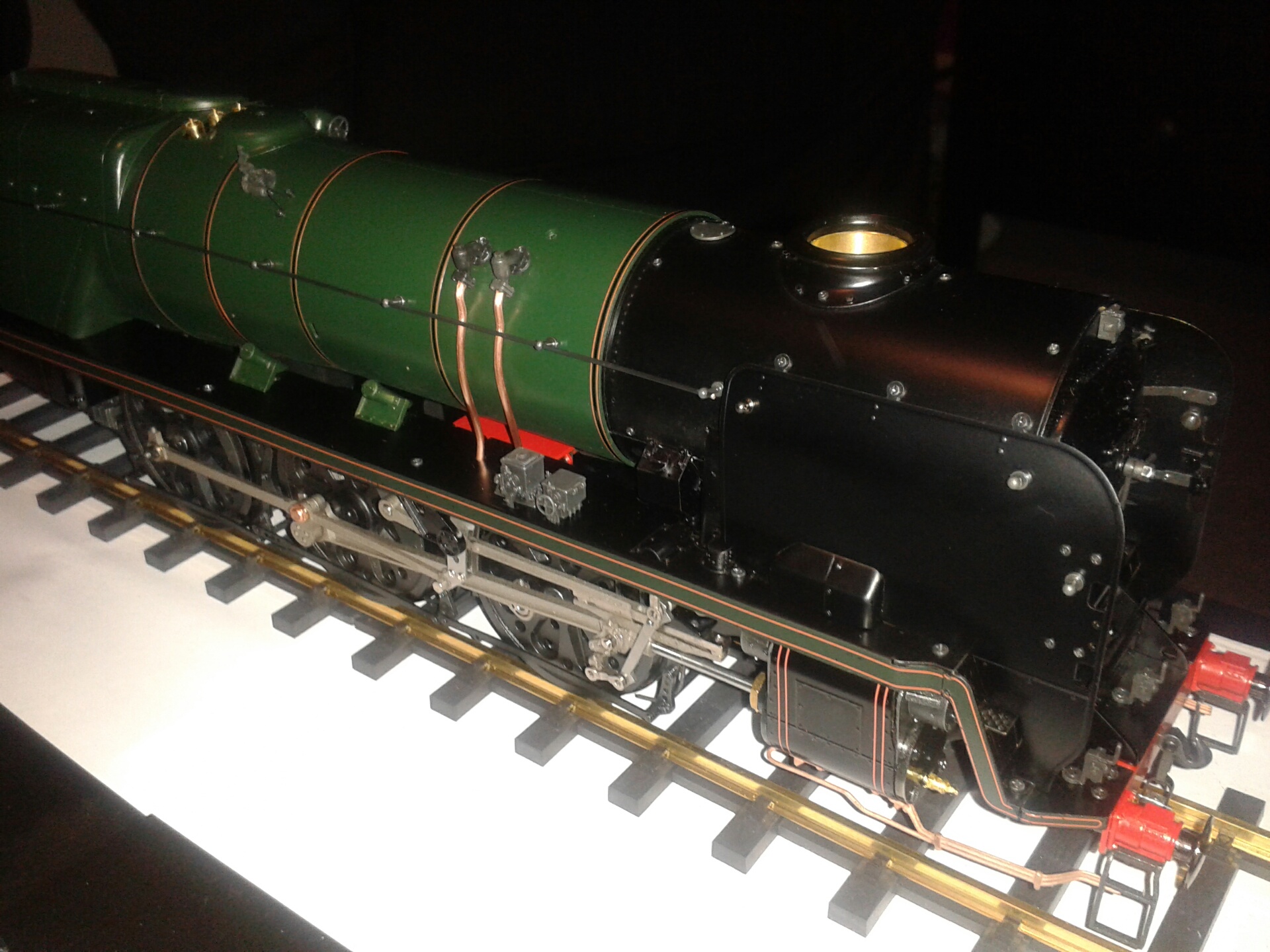
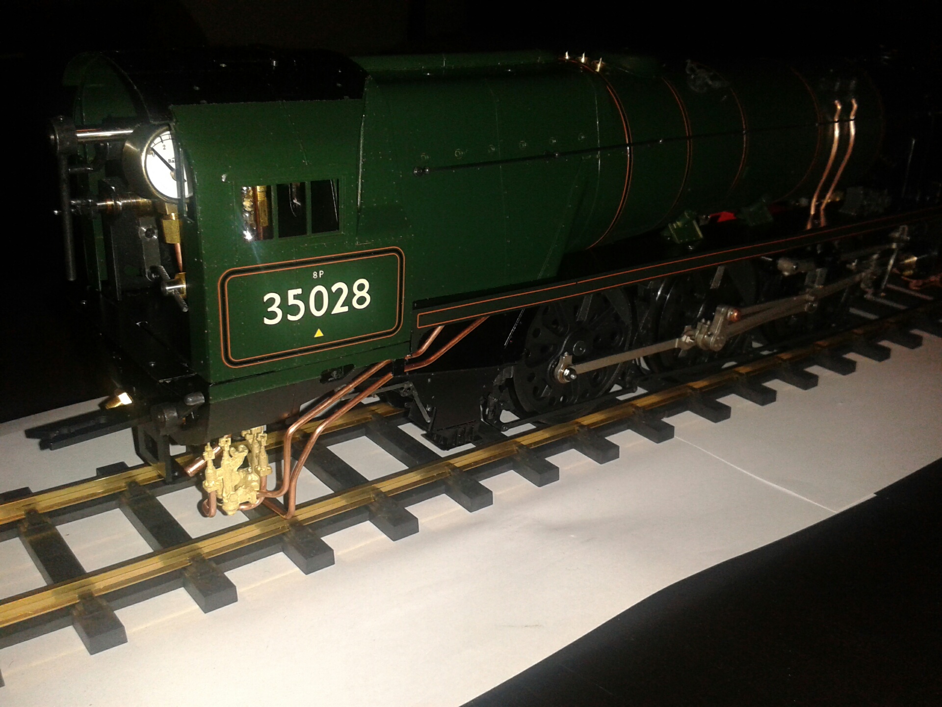
 7/1/15 I fitted the bogie and pony without any problems, and fitted 30 strands of wick into each of the three burner tubes, leaving 12mm projecting above the copper pipes. I also fitted a length of 24 swg piano wire between the whistle and the cab, and I removed the vertical pipe between the right hand lamps on the rear of the tender using a fine diamond-tipped tool in the Dremel (see 20/12 above). This more or less completes the loco - I just need to sort out the cab roof screws, fix the cab, fit the 1mm wire when it arrives, and fit the hoses between loco and tender. The photo shows the end result, and I think it looks superb.
The next step is to sort out the rolling road and give it a test run on the bench before taking it to the track - hopefully next Wednesday, weather permitting.
8/1/15 I made up the three hoses that connect the tender to the locomotive. I cut them so that the outer 5mm hoses hang down fairly close to the rail when the tender coupling is on the outer slot, which I assume is how it is coupled up for running. The pressurised hose taking the output from the handpump turned out to be 50mm long rather than the 70mm shown in the diagram; the other two matched the diagram. I also made up a little bracket to support the rear end of the operating rod for the front damper on the right hand side - there is a M2 threaded hole in the cab floor at the right position for this, and I suspect that a bracket here was intended to be part of the design. I also painted some of the more prominent chemically blackened castings, such as the lubricators and the fittings on top of the smokebox and tender, in satin black (Humbrol 85) to match the black paintwork. The grey finish prior to painting can be seen in the photo, although it looks much more pronounced under the camera flash than in real life.
 9/1/15 The extra lengths of 1mm rod arrived from Andrew today and I fitted the second smoke deflector handrail, the operating rod for the front damper and the pipes along each side of the tender frames. I cranked these at each end to fit behind the tender steps - there is a locating hole behind the front steps - and then fixed them to the tops of the spring hangers with a few dabs of superglue. I'm still waiting for the M1.7 washers from eBay to sort out the projecting screws in the cab roof before I can permanently fix the cab in place.
10/1/15 The washers arrived this morning and I was able to get the screws flush with the cab roof. I then fixed the cab permanently, which completes the build.
First Steaming
10/1/15 I was invited by Garth, who has also just completed his Aster RMN, to visit his garden track so that we could give both engines their first outing - he had already steamed his on his rolling road, but of course I hadn't run at all apart from the air testing. I jumped at the opportunity to have the help of an experienced G1 modeller for my first steaming!
We first of all steamed Garth's engine and ran it without coaches for about 20 minutes - it ran very smoothly, as can be seen in this video. His kit was unnumbered and he has not yet applied the transfers to the cab and tender sides.
We then filled my engine with water and meths (I had previously filled the oil reservoir), pumped water into the boiler with the tender handpump up to about halfway up the glass, turned on the electric blower fan and lit the burners. Within a few minutes the pressure was up to 2 bar and I turned on the steam blower and removed the fan, and soon all three safety valves were lifting at 4 bar on the pressure gauge, so no adjustment was needed. I gingerly opened the regulator but the cylinders seemed full of water - perhaps I had overfilled the boiler. After pushing the engine backwards and forwards a few times with water spurting out of the chimney, it cleared and I set it running gently at walking pace. All seemed well and I was pleased to see oil spots on the smokebox, showing that the displacement lubricator was working. After a few laps light-engine, we coupled up three of Garth's coaches and the result can be seen in this video. I was content to run quite slowly for this first run, but it seemed very smooth and it would start of its own accord without being pushed, so I was very pleased.
The only minor problem was that the axle pump didn't seem to be working consistently. I think this was because the rubber feed hose was kinked, but I'll investigate further when I run on the rolling road. There was also a leak from the front of this hose under pressure, so I'll have to remake the joint to the brass screw fitting.
All in all a very successful first steaming.
11/1/15 I shortened the pump inlet hose to remove the kink, and re-crimped the connector which will hopefully stop the leak. The leak was quite fortuitous because it also happened when the engine was running and so showed that water was being forced back from the axle pump through the inlet clack valve. I removed the banjo bolt and found some stray sealant on the ball seat, and cleaned this up. I started making a base board for my rolling road components and hopefully I'll be in a position to steam on the rolling road tomorrow.
12/1/15 I ran on the rolling road this morning, as shown in this brief video. I tried filtering some rainwater from the garden butt, but it came out coffee-coloured so I ordered 5 litres of distilled water on eBay and used plain bottled water just for this run. We had trouble lighting the burners with a match but my wife managed it eventually, so I've ordered a couple of gas lighters on eBay. I might also order a cyclist's CO2 tyre pump to extinguish the fire, to save blowing down the chimney - Garth uses one of these. The engine ran very well and the kink and leak in the pump inlet hose had been fixed, but the axle pump didn't seem to keep up with the steam consumption. It pumped quite happily into the tender when the bypass valve was open, but I'm not sure how much if any water was going into the boiler with the bypass closed. I'll have to investigate this further.
13/1/15 Today I removed the axle pump and dismantled it to ensure that there was nothing blocking the valves. I didn't find anything suspicious. It's quite tricky to remove and refit the pump with the pipework in place, but I found that I could wiggle it into the space behind the stretcher and under the pipes (as seen from below) and then slide it out from under the pipes. I also removed and checked the wicks, but they looked OK - 30 strands in each burner, projecting 10-12mm. I fitted a piece of neoprene tube over the fuel tank breather, cut at a 45 degree angle and projecting about 1/4" beyond the metal tube to lower the fuel level in the sump, as recommended on the forum by Dave Stick - he had found that the burners tended to flood without this. I then had difficulty lighting the burners and wasn't able to raise steam, not helped by the gusty wind, and so I'll try again tomorrow perhaps with a shorter tube extension. I've noticed that the engine is very sensitive to being on a slope - my garage floor slopes gently down from back to front, as is common with integral garages. With the engine pointing down the slope the burners were definitely flooding and the water transferred itself from the tender to the boiler. I'll position it across the slope tomorrow. I've also ordered a dentist-type mirror on a stick from eBay so that I can check what the burners are doing.
14/1/15 This afternoon I succeeded in raising steam by the expedient of closing the garage door to keep the wind at bay until I had pressure. The engine then ran steadily for twenty minutes or so with the safety valves just lifting gently, and the axle pump more than kept up with the steam consumption - I had the bypass open for half the time and used a tankful of water and ended with the gauge glass almost full. I'm not sure now whether Monday's problem was something wrong with the pump or just excessive steam production, including periods stationary with the blower open and the safeties blowing vigorously. I also noticed that it seemed to run better with the reverser turned back a turn from full forward gear, so my earlier concerns when setting the valves that the valve ports were not uncovering completely turned out not to be an issue.
 I'll now clean the engine up and wait for a suitable day to take it down to the track at Colney Heath.
18/1/15 I ran again on the rolling road this morning, mainly to try out reverse gear which I'd forgotten to do previously, and also to try out my new purchases from eBay - 6 one-litre bottles of bio-ethanol from EkoFuel, a gas lighter and a mirror to inspect the fire, along with the 5 litres of distilled water. All worked well and the mirror was particularly useful. I coloured the fuel with green food colouring to avoid mistakes. I'm not now using the breather tube extension - I don't seem to need it as long as the engine and tender are on the level.
20/1/15 I've just been down to the track - they now run G1 on Tuesdays as well as Wednesdays - but it was all locked up. Although I do have a key I didn't want to use the track for the first time with nobody else present, so after waiting until 11.30 I gave up and went home. Rather disappointing - it's a nice sunny windless day, albeit very cold. The forecast for tomorrow is snow, so it looks as though I'll have to wait until next week.
21/1/15 The threat of snow receded, so I went down to the track this morning and found four other hardy souls there, with two engines running. I steamed up and did a couple of laps light engine, then borrowed a rake of six coaches and gave it a go. The engine pulled them round steadily although rather slowly - the consensus was that the extremely cold weather (2 degrees C) probably wasn't helping. Unfortunately I didn't get a chance to take a video. However after a few laps we began to notice some steam leaking from under the front end, and the engine was running a bit unevenly. The leakage happened even in mid-gear, and at all points of rotation, so I suspect that it's in the middle cylinder steam pipe or valve chest. I'll have to steam on the rolling road and investigate more carefully, but I fear that a lot of dismantling may be needed to get at the problem.
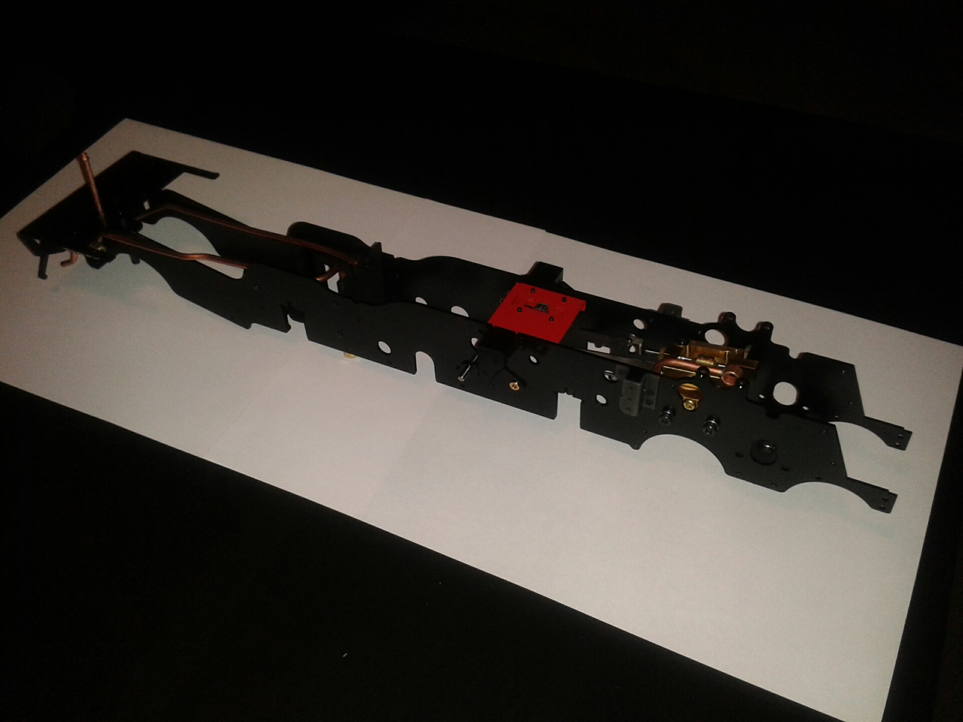
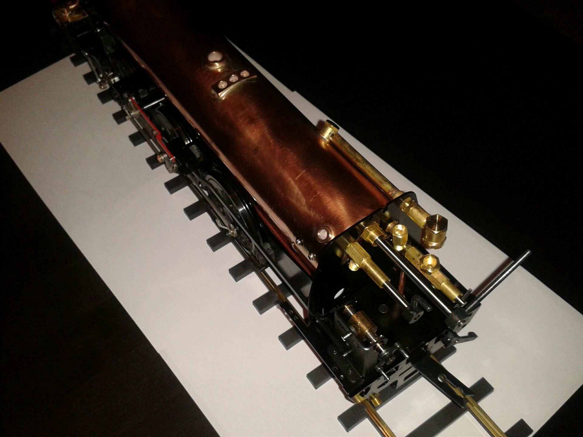
 22/1/15 I reported the problem on the forum and Dave Stick told me of several cases where the gland nut on the middle valve chest had come loose. I started dismantling and it took me under an hour to remove bogie, smoke deflectors, smokebox, running boards, superheater, steam pipes, saddle and exhaust manifold, as shown in the photo. I suspect that it will take somewhat longer to reassemble! The gland nut on the valve chest was indeed slightly slack, but unfortunately it appeared to be screwed fully in and so I assumed that the leak must be from the gaskets and I removed the valve cover which destroyed the top gasket. Only then did I put a spanner on the gland nut and find that it was quite loose and I could do it up half a turn, so that must have been the problem. The photo shows the gland nut fully unscrewed. I'll reassemble it with Loctite 222. I've asked Andrew at Aster if he can supply a new pair of gaskets - I could make my own from paper, but given the amount of time needed to dismantle and rebuild it it seems safer to use the genuine article. The use of oil rather than sealant on the gaskets as mentioned in Step 1 above does seem to have produced a good seal.
23/1/15 I remembered that when I originally assembled the middle valve chest I had to back off the gland nut slightly to avoid the O ring locking solid, which probably explains why the nut had worked loose, so I decided that I'd better remove the valve chest so that I could check for free movement as I adjusted the gland nut. I found that it still locked up if the nut was tightened and it needed backing off by about 1/8th of a turn. Dave Stick advised me to use silicone grease in the gland and this improved it greatly, but I felt it was still too stiff for comfort when completely tight - I don't want to strain the valve gear. I backed it off by a tiny amount, perhaps just 10 degrees on the nut, with threadlock to secure it. This gave a nice smooth motion with enough drag to show that the O ring was sealing properly. Andrew didn't have any gaskets in stock so I made my own from a brown Manila envelope and soaked them in oil. It was extremely difficult to refit the pin joining the valve rod to the combination lever and I thought that I might have to remove the boiler, but eventually I managed it by supergluing the head of the pin to a brass rod that I poked through the hole in the chassis, with another tapered rod to lift and hold the lever in the right position through the hole on the other side. Once the thread had caught I applied threadlock to the hole and used a tubular spanner to tighten the pin. I then reset the valve timing, and refitted the valve cover and then the exhaust manifold and the saddle. Hopefully I'll rebuild everything else tomorrow ready for a test on the rolling road.
24/1/15 I'm pleased to say that it's all back together again and steaming smoothly on the rolling road with not a wisp of steam from underneath. The only slight concern is that I have an M1.7-3 screw left over! It took an hour to dismantle and 3-4 hours to reassemble. The smokebox now slides in and out with no problem at all.
29/1/15 I didn't go to the track yesterday because it was so windy that I thought it would be difficult to light the burners. However, I have now joined G1MRA and I went to my first meeting of the Chiltern group yesterday evening. There were about a dozen members there and Garth had his RMN on show.
4/2/15 I took the engine down to Colney Heath this morning despite the very cold and breezy weather, and had a good run for about half an hour, getting through one tankful of fuel and several tanks of water. Everything seemed to be working well. I made up a fire lighter consisting of a few strands of wick held in the end of a twisted copper wire, dipping this in fuel and manoeuvering it into place alongside the burner tubes before applying the gas lighter. This seemed to help - the pony truck makes it quite tricky to get the lighter flame up near the wicks. Unfortunately I wasn't able to borrow any coaches - I must order a set of my own from G1 Model Co. I just need to decide which colour to have - SR green is the obvious choice for the RMN, but they might not go so well if I ever get another engine.
12/2/15 It was quite busy at Colney Heath yesterday and I had to book a half hour slot and wait my turn, even with three simultaneous running tracks. I had the annual steam test done and was given a certificate which may be needed if I run elsewhere. The engine was running nicely but still a bit sluggish when hauling the six club coaches - perhaps it still needs more running-in. I think I'll try removing one or two of the wicks from each burner and see if that gives more power, although the pressure does seem to stay pretty well up to the 4 bar level.
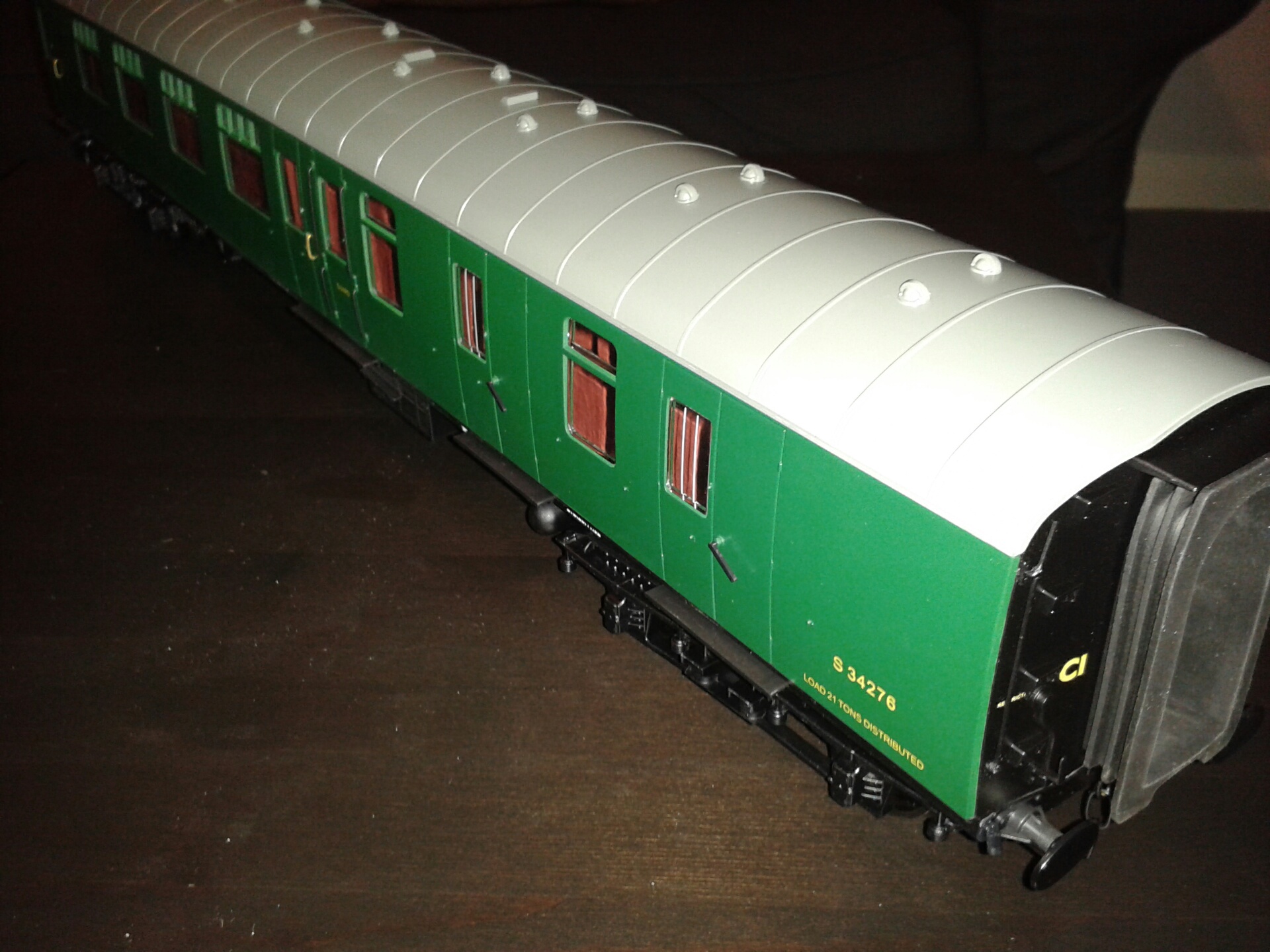 16/2/15 I ordered a set of four coaches in SR green from the G1 Model Co on Friday and they arrived today. They are nicely finished with full interior detail. The roof appears white in the camera flash but is mid grey in reality. I ran the engine on the rolling road yesterday to show my son and grandson, and I noticed that when running fast the pressure did fall away from the 4 bar mark, suggesting that the burners are not strong enough. Today I removed three strands of wick from each of the burners to leave 27, and I'll take the engine and the new coaches down to the track tomorrow (Tuesday) to see how they run.
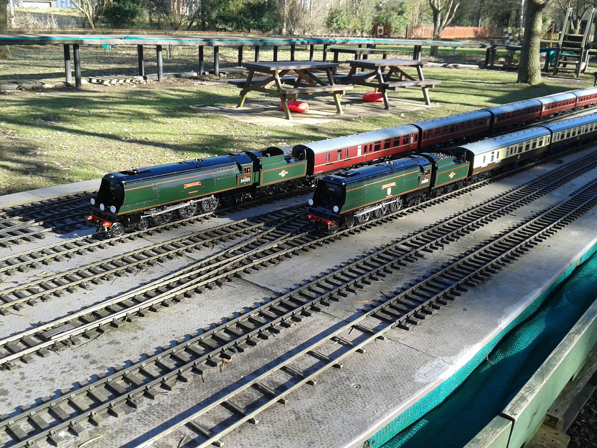 17/2/15 I ran at Colney Heath today with my four new coaches, alongside the two Aster 'Spamcans' each with six or eight G1M Co coaches shown in this photo. Reducing the wicks to 27 strands didn't really seem to have improved things and the performance was still quite sluggish - much slower than the two Spamcans which were cruising round at a good speed with their safety valves gently lifting. The consensus was that my burners were just not strong enough. I tried with the fuel from one of the Spamcans in case there was anything wrong with my bio-ethanol, but there was no significant difference. I will try removing further strands of wick as the next step - one of the Spamcans was running with 22 strands, although I'm not sure if its burners are the same size. I did take a video of my engine crawling along, but it's too embarrassing to show here!
20/2/15 I took my engine round to Garth's house today and ran on his garden railway. I had reduced the wick strands to 24 in each burner and we used his IDA (industrial denatured alcohol) meths to see if that gave better results than my bio-ethanol. The performance seemed a little bit better than on Tuesday - I was able to pull five of Garth's heavy brass coaches, but only rather slowly. It cruised around quite happily without the coaches. Garth felt that the performance was still not as good as it should be, so the fuel is not a major issue and the reduction in the wicks may have helped a bit. He was happy that the engine was free-running, so the problem is not excessive friction. We took the burners out and he was happy with the state of the wicks. We checked the height of fuel in the burner tubes by measuring the clearance under the burners with the engine standing on a flat surface, then taking the burners out, packing them up to the same height and connecting them to the tender feed without the wicks. The fuel rose fairly near the tops of the tubes, so was a bit on the high side. This shouldn't detract from performance but it would be safer to have the level a bit lower, about halfway up the tubes, so I may revert to fitting an extension over the tank breather as discussed on 13/1 above. There was no problem with the fuel flow rate from the tank. I think the next thing to check is the sealing of the smokebox - I'm pretty sure that I sealed it properly, but I will remove the smokebox and double check, and perhaps put some sealant around the rear joint.
21/2/15 I've just been looking at the valve gear and I think I've found the likely cause of the performance problem. The lifting arms seem to have moved on the weighshaft so that when the left side is in neutral, the right side is some way into forward gear and the middle is well into reverse! In full forward the middle cylinder wouldn't have been doing much if anything, and the right would have been over-reaching and probably wasting steam. The grub screws on the weighshaft were still tight and I'm absolutely certain that I lined the arms up carefully and correctly when I built it - hence the decent performance on the very first run at Garth's track. I think the problem is that when adjusting the reverser it can be really quite stiff as it tries to move the radius rod in the expansion link that's at a sharp angle, and this probably caused the slippage. I've now realigned things and tightened the grub screws as hard as I reasonably can. Probably rolling the engine gently backwards and forwards when moving the reverser would reduce the strain. I'd noticed that when I first ran the engine it always self-started, but more recently it didn't always do so, which should have pointed me to the problem. I'm not sure that running on the rolling road will prove much, but hopefully I'll be able to try it at Colney Heath next week.
25/2/15 I ran at Colney Heath today and the results were a little disappointing. The performance had improved a bit, but not as much as I had hoped. Running without coaches it was absolutely fine - racing around the track at breakneck speed. However, with my four coaches it was still struggling and losing pressure. I think the valve timing was OK - by pushing the engine along slowly with the regulator open I could feel six exhaust beats up the chimney per revolution. It ran for 45 minutes on one tank of fuel, which suggests that it's probably not consuming enough. I have still to remove the smokebox and check the sealing. I might then replace the wicks and make them slightly longer - Garth told me that someone else had done this to cure a performance problem.
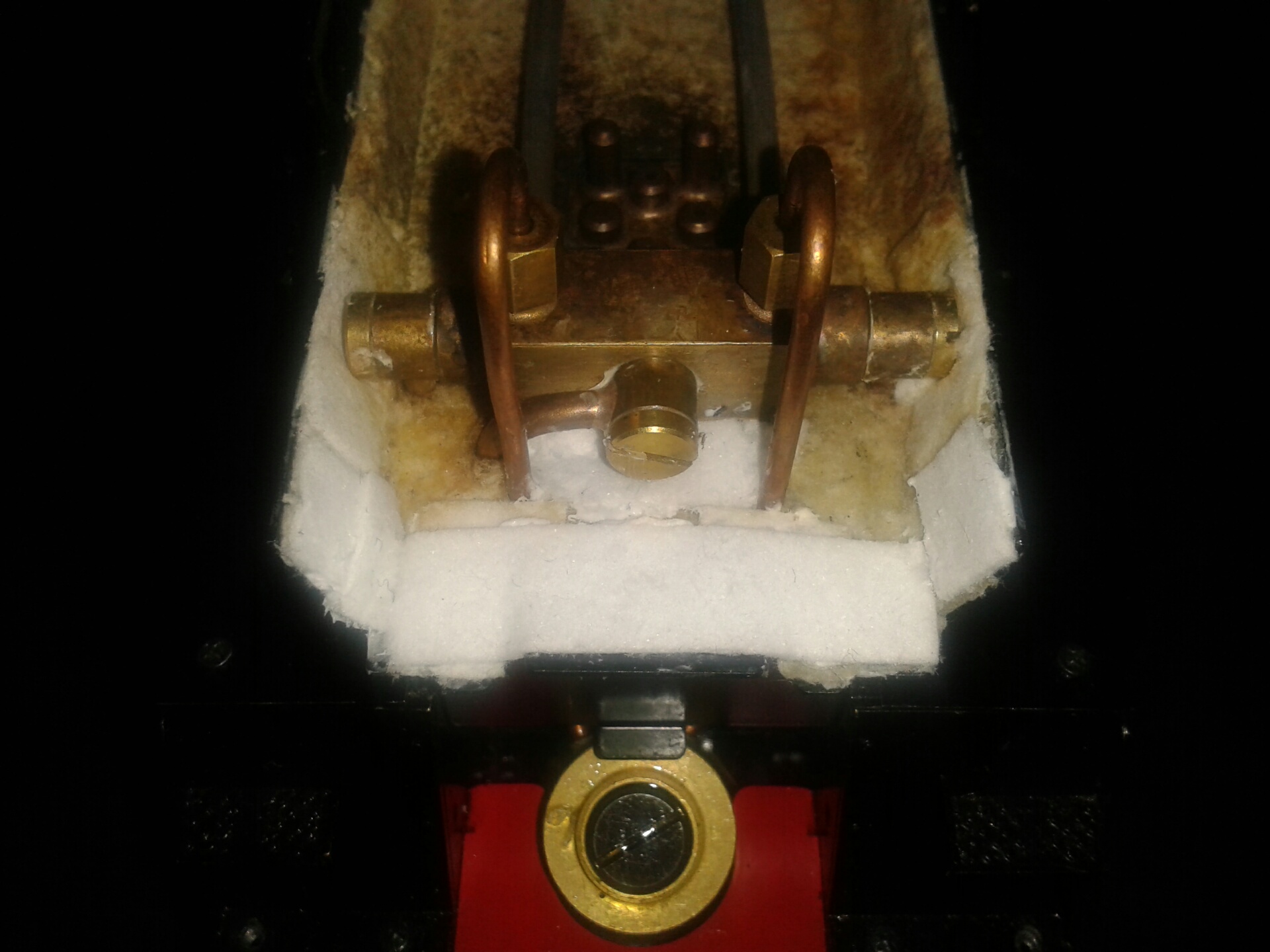 26/2/15 I've removed the smoke deflectors and smokebox and I did find some small gaps in the insulation around the steam pipes and oil pipes at the front end. In cases where there was a slit in the ceramic sheet to allow entry of the pipes, the material around the slit seems to have eroded away and left a wider gap. The photos in Step 11 above show the insulation in its pristine state - this photo shows the front end after patching over the slits with strips of insulation held down with plenty of sealant. Just to be safe I've also added a second narrow strip around the rear end of the smokebox roof insulation where it butts up to the circular plate on the front of the boiler, although I don't think there was any gap here. The fact that the insulation had eroded away suggests that there must have been quite some rush of air through the slits, so hopefully the repairs will make a difference. The original insulation is surprisingly dirty after just a few hours running - quite a lot of water is blown up through the exhaust when starting a run. I'll try on the rolling road tomorrow to see if I can detect any improvement in the burner strength.
27/2/15 I ran on the rolling road this morning after sealing the smokebox but without changing the burners, and the fire seemed slightly stronger but not dramatically so. I then spoke on the phone to Jack W who has had similar issues with his RMN and has fixed them with Andrew's help by fitting longer wicks. I therefore removed the burners and fitted new wicks with 24 strands in each tube projecting a full 15-16mm. I previously had 24 strands projecting 10mm (incidentally I trimmed the old wicks down from 12 to 10mm when I went down from 30 to 27 then 24 strands, which may with hindsight have been counterproductive). The difference in performance on the rolling road was quite marked - the burners were noticeably stronger seen in the mirror, I couldn't hold my hand 6" above the chimney when it was running, and the safety valves were blowing off very vigorously all the time. This was definitely the biggest improvement that I've seen from any of the changes that I've tried, so I'm very hopeful that the performance on the track will be much better next week.
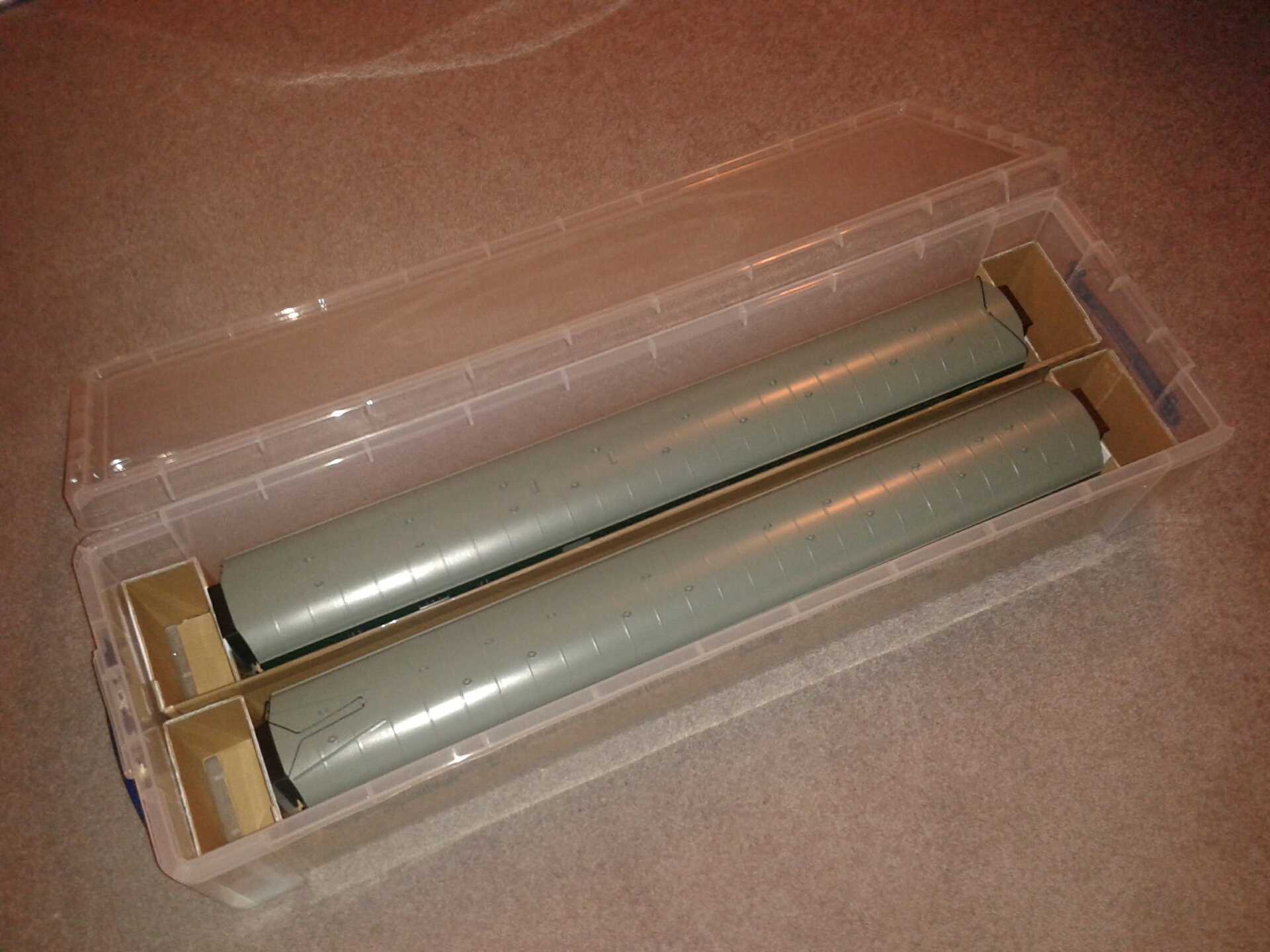 4/3/15 I ran at Colney Heath yesterday in cold and very windy conditions. The performance was excellent, as shown in this video. I shall now be able to invest in a couple more coaches! The burners did seem a bit erratic and the performance wasn't as good as this for the entire session, but this could well have been caused by the strong wind - others were having difficulty even raising steam - so I won't try any further changes until I've run in more benign conditions. It's very satisfying to see the engine performing as it should.
5/3/15 I ordered two more coaches from G1 Model Co today to add to my rake of four. I also ordered another of these storage boxes, on offer at 10, which are just the right size to hold two coaches side by side.
11/3/15 I ran again at Colney Heath this morning - the weather was a bit warmer than last time, with just a moderate breeze. It ran very well with my six coaches as shown in this video. The fuel lasted for just over half an hour, so it is now using more fuel than it used to with the old wicks which is a good sign. The pressure stayed at 4 bar all the time and it maintained the water level with the pump bypass just very slightly open. The speed responded well to the regulator. It would self-start even when pulling the six coaches, and I was overtaking other trains which made a change! The general consensus was that it was running very nicely.
7/4/15 I ran at Colney Heath today after a four-week gap caused by a combination of holidays and bad weather. The weather today was really pleasant - warm and windless - and there was a good turnout. The engine was again running very well and at one stage it was going far too fast, with people shouting warnings about imminent derailment! This video shows it running at a more reasonable pace, with Nigel's Aster West Country in hot pursuit.
14/4/15 I ran again this morning and all went well. The weather was really quite hot and there was a good turnout for a Tuesday. I was more careful with the regulator after last week's runaway scare and ran at a very steady pace. The engine is definitely using less water than it used to and I can leave the bypass partly open all the time, which I couldn't before, so something must be more efficient - perhaps the reverser setting, which is wound back a bit from full forward, and perhaps a result of running-in - it now rolls very smoothly and easily. Garth was also there today, running a very nice coal-fired Rebuilt West Country. No video this time - sorry.
27/5/15 I ran at Colney Heath today (and I also ran a couple of weeks ago, but omitted to update the website). I had added one extra strand to each of the wick tubes, making 25 strands in each, in order to try and reduce the intensity of the burners and increase the running time, but it was difficult to say whether there was any real difference. The engine ran nicely and I kept the speed down to a realistic scale level. I recently bought 10 litres of distilled water for 10.75 inc postage from this eBay supplier, which I thought was very good value.
17/6/15 I ran at Colney Heath this morning and it seemed less busy than of late - I turned up at 11.40 and got a half-hour slot at 12.00. The engine was running well, as shown in this video. I've bought one of these fuel bottles on eBay, which is a quicker way of filling the tank than the little funnel provided in the kit, which I had lost on the last outing.
27/10/15 I steamed at Colney Heath this morning and there was a reasonable turnout on a warm sunny late October day, with an Aster Castle and Nigel's Aster West Country among others. The engine was steaming nicely - I've run a few times since my last website update, sometimes with rather sluggish performance, but I went back down to 24 wicks per tube before this run,which seemed to make the fire stronger. The video is taken from the far side of the track this time.
28/1/16 I steamed at Colney Heath this morning for the first time in three months. The weather was bright and cold with a bit of a breeze and some of the others seemed to have a bit of trouble keeping the pressure up, but my RMN was steaming nicely once I got the fire lit.
5/4/17 I ran at Colney Heath this morning for the first time this year. The engine was steaming very nicely, better than it has done for the last few outings - it hadn't been using as much steam oil as it should, but this time it seemed fine and there was a film of oil on top of the boiler so whatever was causing the obstruction seems to have cleared. I have changed to the thicker 460 steam oil in place of 220, which may have helped.
26/02/26 After many years of inactivity I have decided to sell my Aster RMN and the six SR green carriages. I steamed up the loco on the rolling road a couple of weeks ago to check that it still ran nicely, which it did, and I have sold them to Station Road Steam who also handled my Britannia a few years ago. The loco is listed here and the carriages appear to be sold already and are on the archive.
27/02/26 The loco also now appears to be sold and is on the SRS archive here. The new owner is welcome to contact me using the email link on my home page.
| Previous | Index |