 19/06/06
I ordered kit 15 this morning.
19/06/06
I ordered kit 15 this morning.
19/06/06
I ordered kit 15 this morning.
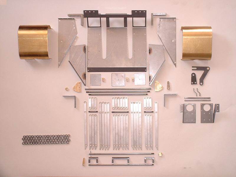
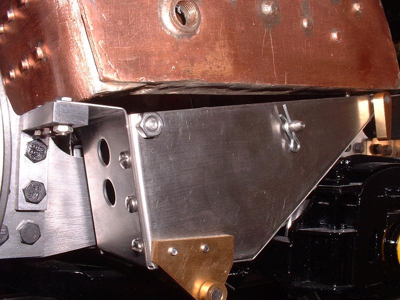
20/06/06 Kit 15 arrived at 8.40 this morning. It consists of the ashpan and grate, together with replacements for the incorrect axle pump link and steam brake crank that I mentioned in kits 9 and 10 respectively, and the replacement lubricator mounting brackets, brass covers for the cylinders, and drain cock links. The ISO drawings were not included with the instructions, so I've asked Debbie for these and she has put them in the post. Fortunately I have my picture of the control model at Harrogate which has enabled me to lay out the contents in hopefully the right sort of positions for this photograph. All the parts seem to be present and correct. The instructions seem to relate to the earlier Winson verson of the kit, which only had one central set of hinged grate bars instead of the three sets in the new version, and where the locking pin for the grate bars went through holes in the bars rather than underneath the bars. However, the photograph of the control model makes everything pretty clear.
 21/06/06
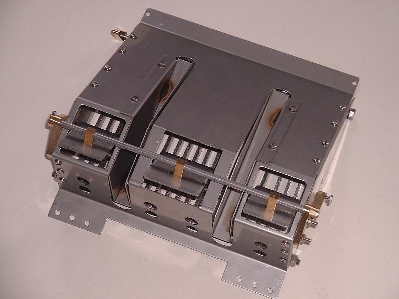
I did a trial assembly of the ashpan and grate, and fitted it to the frames - it went together quite easily. The photograph shows the underside with the three rotating shutters for emptying the ashpan. The front of the ashpan is secured to two brackets bolted through the top rear bolt holes of the rear stretcher - the M5x16 bolts provided only engage the brass stretcher by a couple of turns, and need to be replaced by M5x20. The rear end rests on two further brackets mounted just in front of the drag frame, but it is not bolted to these brackets - perhaps to allow for expansion when the grate gets red hot. The rod carrying the three shutters needs to be slid through the gap between the pony truck and the underside of the rear frames, and under the cylinder cock operating rod, before being fitted into the bearings on either side of the ashpan. I was a bit concerned that the modified spring carriers on my freshly painted pony truck might foul the underside of the ashpan, but there is a clearance of several millimetres. I see that Jason has placed an order for the forthcoming Modelworks Duchess, and has started a Duchess Builder website to record progress.
21/06/06
I did a trial assembly of the ashpan and grate, and fitted it to the frames - it went together quite easily. The photograph shows the underside with the three rotating shutters for emptying the ashpan. The front of the ashpan is secured to two brackets bolted through the top rear bolt holes of the rear stretcher - the M5x16 bolts provided only engage the brass stretcher by a couple of turns, and need to be replaced by M5x20. The rear end rests on two further brackets mounted just in front of the drag frame, but it is not bolted to these brackets - perhaps to allow for expansion when the grate gets red hot. The rod carrying the three shutters needs to be slid through the gap between the pony truck and the underside of the rear frames, and under the cylinder cock operating rod, before being fitted into the bearings on either side of the ashpan. I was a bit concerned that the modified spring carriers on my freshly painted pony truck might foul the underside of the ashpan, but there is a clearance of several millimetres. I see that Jason has placed an order for the forthcoming Modelworks Duchess, and has started a Duchess Builder website to record progress.
22/06/06 I polished and fitted the replacement brake crank and axle pump link. The new brake crank has a brass bearing which is a good fit on the pivot bolt. The axle pump link is 3mm longer than the original, which agrees pretty well with my earlier calculations of the pump stroke. I tried fitting one of the brass cylinder covers, but I'll probably leave them off given that I've already polished the cast iron to a very smooth finish. They don't lie perfectly flat against the outer face, and hence leave a slight gap on the front and rear faces. Ted has pointed out that the top screw holes need to be plugged if the covers aren't fitted, since they go right through into the exhaust ports.
23/06/06 I dismantled the ashpan and grate and started to polish the parts. I'm planning to go and do another day's work on the Oliver Cromwell restoration at Loughborough tomorrow.
24/06/06 I spent the day at Loughborough, and my notes and pictures are shown here.
 25/06/06
I polished and assembled the stainless steel ashpan. The thick brass brackets bolted to the lower front of the side plates to carry the shutter pivot rod are rather unsightly and seem to have been added as an afterthought, since they cover holes that look as though they were intended to carry the pivot rod above rather than below the shutters. The right-hand bracket will probably be covered by the dummy exhaust steam injector, but I might try to substitute something less obtrusive on the left-hand side, or perhaps just fix the bracket on the inner face and cut a gap in the shutter frame for it.
25/06/06
I polished and assembled the stainless steel ashpan. The thick brass brackets bolted to the lower front of the side plates to carry the shutter pivot rod are rather unsightly and seem to have been added as an afterthought, since they cover holes that look as though they were intended to carry the pivot rod above rather than below the shutters. The right-hand bracket will probably be covered by the dummy exhaust steam injector, but I might try to substitute something less obtrusive on the left-hand side, or perhaps just fix the bracket on the inner face and cut a gap in the shutter frame for it.
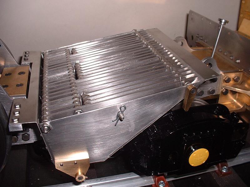
26/06/06 I draw-filed and polished all the grate bars, and reassembled them. After removing the burrs from the bars and spacers, I found that I needed an extra half-thickness spacer at each end of the front and rear rods to keep the grate central in the ashpan. Fortunately there were exactly four spare spacers in the kit. The ends of the rods at the front of the three hinged sections needed filing flush with the nuts to avoid them catching as the grate is raised from the dropped position. The mechanism works nicely, and should allow the fire to be dropped quickly in an emergency by pulling out the pin that supports the hinged sections.
 27/06/06
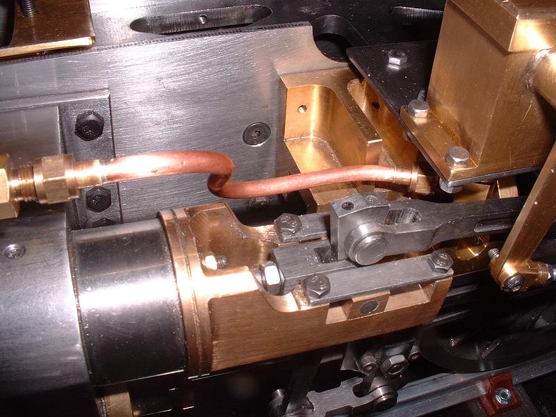
Debbie sent me the temporary dummy cylinder cocks and I fitted these along with the linkage, which works nicely. I also fitted the left-hand lubricator on its new bracket and bent the pipe to connect the lubricator to the check valve on the cylinder steam pipe. It takes some care to put three separate bends in the pipe and end up with the pre-soldered unions in the correct position - as Julia remarked recently in her excellent Burrell Builder's Diary, it might be easier to bend a length of pipe first, and then cut it to length and solder the unions on afterwards. I started to fit the lubricator operating linkage which consists of a crank on the expansion link spindle linked by a rod to the lubricator pump arm. The expansion link spindle is barely long enough to take the crank and a locknut, and the holes in the pump arm and its clevis appear to need drilling out to 3mm to take the pin supplied. Also the rear clevis needs some filing of its slot to allow it to rotate far enough around the crank arm. I'll double-check all this before making the necessary changes.
27/06/06
Debbie sent me the temporary dummy cylinder cocks and I fitted these along with the linkage, which works nicely. I also fitted the left-hand lubricator on its new bracket and bent the pipe to connect the lubricator to the check valve on the cylinder steam pipe. It takes some care to put three separate bends in the pipe and end up with the pre-soldered unions in the correct position - as Julia remarked recently in her excellent Burrell Builder's Diary, it might be easier to bend a length of pipe first, and then cut it to length and solder the unions on afterwards. I started to fit the lubricator operating linkage which consists of a crank on the expansion link spindle linked by a rod to the lubricator pump arm. The expansion link spindle is barely long enough to take the crank and a locknut, and the holes in the pump arm and its clevis appear to need drilling out to 3mm to take the pin supplied. Also the rear clevis needs some filing of its slot to allow it to rotate far enough around the crank arm. I'll double-check all this before making the necessary changes.
28/06/06 I made the above changes to the lubricator linkage and also tapped out the M3 holes in the clevises so that the threaded ends of the rod go in to their full depth. Ted tells me that he filed down the locknut for the expansion link crank and fitted it underneath the crank, and I will probably do the same. I tested the lubricator with light machine oil and found a slight leak from the outlet pipe adaptor, so I dismantled it and sealed it with PTFE tape. I started fitting the right-hand lubricator.
29/06/06 I fitted the right-hand lubricator and its pipe and linkage. The pipe bends are perfectly symmetrical on the two sides - it will be a shame to cover them up with the running boards. The lubricator didn't work when I tried it, so I dismantled it and it turned out that the spring under the ball valve was too long and hence too strong - I hadn't shortened it by 2mm as with the first lubricator (see kit 13, 24/5/06) because it seemed at the time to be the right length, but shortening it cured the problem. This completes kit 15, and I now need to wait for Modelworks to deliver the replacement driving wheels and the replacement motion gear, and kit 16 which is the boiler. We'll be away sailing for the next few days, so no more updates until Monday.
 3/7/06
Just back from a few days sailing - the water is definitely the place to be in this heatwave. We spent Saturday evening anchored in an idyllic remote corner of Poole harbour, far from the agonies of England's penalty shoot-out in the World Cup (although cheers and groans, ending with a final big groan, could be heard from other boats in the anchorage, so I deduced what the result must be). I've heard nothing more from Modelworks, so I'll continue with painting and other odd jobs this week.
3/7/06
Just back from a few days sailing - the water is definitely the place to be in this heatwave. We spent Saturday evening anchored in an idyllic remote corner of Poole harbour, far from the agonies of England's penalty shoot-out in the World Cup (although cheers and groans, ending with a final big groan, could be heard from other boats in the anchorage, so I deduced what the result must be). I've heard nothing more from Modelworks, so I'll continue with painting and other odd jobs this week.
5/7/06 I've airbrushed another 'final' coat of paint on the bogie wheels and the pony frames. I've decided to have a go at soldering the joints on the tender tank rather than using the sealant provided - Ian told me recently that he did this successfully. I'll start with the joint around the inside of the front bulkhead, which will not be visible if I make a mess of it.
11/7/06 Debbie tells me that the new batch of driving wheels is ready and she is sending out my replacements today, so other builders who are waiting for replacement wheels might like to check with Debbie.
15/7/06 Just back from a few days sailing in the Solent. My replacement driving wheels have arrived, along with the replacement return cranks and eccentric rods, so I should now be able to complete the assembly of the motion and test on air. Ted tells me that he has also received the replacement parts and is hoping to test on air within the next few days. I also had a letter from Modelworks saying that construction of the boilers is well under way and the first batch should be ready by the end of July. I'll write up the completion of the motion under kit 13, so please check that page for the next few days (or maybe weeks!)
 10/6/07
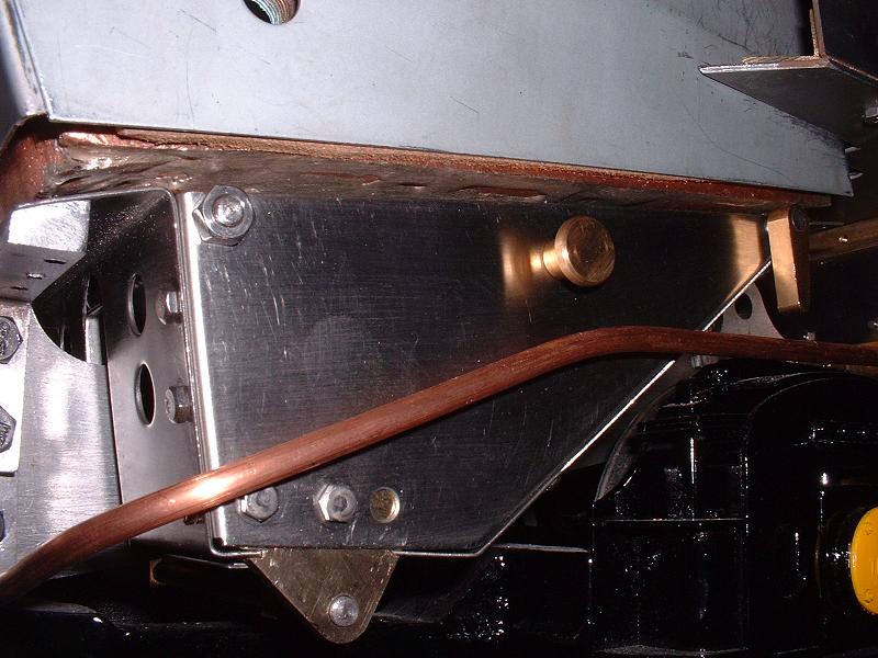
There's quite a large gap between the bottom of the firebox and the sides of the ashpan, as shown in this photo - about 8mm at the front and 3mm at the rear. I think this will spoil the draughting and perhaps even let the fire out through the gap. The problem is caused by a combination of the lower front edge of the firebox protruding below the foundation ring, and the front flange on the ashpan being horizontal rather than angled in line with the sides. Ted and Richard have both told me that they have the same problem, and indeed Ted has already made stainless steel inserts to fill the gap. I may well do the same, although I'll also investigate changing the angle of the front flange behind the fixing bolts. I'll wait until I have the firebox cladding to check the fit.
10/6/07
There's quite a large gap between the bottom of the firebox and the sides of the ashpan, as shown in this photo - about 8mm at the front and 3mm at the rear. I think this will spoil the draughting and perhaps even let the fire out through the gap. The problem is caused by a combination of the lower front edge of the firebox protruding below the foundation ring, and the front flange on the ashpan being horizontal rather than angled in line with the sides. Ted and Richard have both told me that they have the same problem, and indeed Ted has already made stainless steel inserts to fill the gap. I may well do the same, although I'll also investigate changing the angle of the front flange behind the fixing bolts. I'll wait until I have the firebox cladding to check the fit.
14/6/07 Just back from a few days on the boat. The weather looks set to keep us off the water for the next few days, so I might go up to Loughborough on Saturday if it's not too wet. I've suggested to Debbie that Modelworks make some new side plates for the ashpan, to raise up the top edge and the grate flush with the bottom of the firebox.
12/12/07 There's been no sign that Modelworks are going to do anything about the gap around the ashpan, so I've decided to fix it myself. I'll bend down the front flange and angle the tops of the supporting brackets to match. I'll also elongate the holes on the front of the ashpan sides and move the sides up a couple of mm to bring them level with the front flange. Harry W did something very similar and he sent me a photo of the result, which looks very neat.
 14/12/07
I've bent the flange down to an angle somewhat below the line of the ashpan top, using the 18" mini bending brake from Chronos that I bought for the cab platework. I modified the front supporting brackets by soft soldering a strip of 1/8" x 1/4" steel on the rear half of each top face, then cutting and filing the top faces to an angle of about 30 degrees to match the flange. I then plugged the existing M3 holes from below and redrilled them perpendicular to the top face, with countersunk holes in the flange. I've also moved the left-hand bracket for the shutter spindle to the inner face of the ashpan side, cutting a piece out of the shutter frame to accommodate it. I'll leave the right-hand bracket on the outside since it is covered by the dummy exhaust steam injector. I also moved the retaining collar from the outside of the left-hand bracket to the inside of the right-hand bracket, and trimmed the spindle flush with the left-hand bracket. The photo shows all these improvements - the ashpan is now within 1mm of the foundation ring all round. One slight snag is that with the grate close up under the foundation ring, the outermost grub screws on the rotating section of the grate foul the underside of the firebox and need to be shortened to be flush in their fittings. The rear ends of the outermost moving grate bars, which rise up when the grate is dropped, can also touch the sides of the inner firebox unless it is precisely central over the grate, so I'll trim these to avoid the risk of the grate not dropping when the pin is pulled out. The photo taken on 26/6/06 above shows the protruding grub screws and the moving grate bars.
14/12/07
I've bent the flange down to an angle somewhat below the line of the ashpan top, using the 18" mini bending brake from Chronos that I bought for the cab platework. I modified the front supporting brackets by soft soldering a strip of 1/8" x 1/4" steel on the rear half of each top face, then cutting and filing the top faces to an angle of about 30 degrees to match the flange. I then plugged the existing M3 holes from below and redrilled them perpendicular to the top face, with countersunk holes in the flange. I've also moved the left-hand bracket for the shutter spindle to the inner face of the ashpan side, cutting a piece out of the shutter frame to accommodate it. I'll leave the right-hand bracket on the outside since it is covered by the dummy exhaust steam injector. I also moved the retaining collar from the outside of the left-hand bracket to the inside of the right-hand bracket, and trimmed the spindle flush with the left-hand bracket. The photo shows all these improvements - the ashpan is now within 1mm of the foundation ring all round. One slight snag is that with the grate close up under the foundation ring, the outermost grub screws on the rotating section of the grate foul the underside of the firebox and need to be shortened to be flush in their fittings. The rear ends of the outermost moving grate bars, which rise up when the grate is dropped, can also touch the sides of the inner firebox unless it is precisely central over the grate, so I'll trim these to avoid the risk of the grate not dropping when the pin is pulled out. The photo taken on 26/6/06 above shows the protruding grub screws and the moving grate bars.
| Next Kit | Previous Kit | Index |