 3/4/06
I ordered kit 11 this afternoon.
3/4/06
I ordered kit 11 this afternoon.
3/4/06
I ordered kit 11 this afternoon.
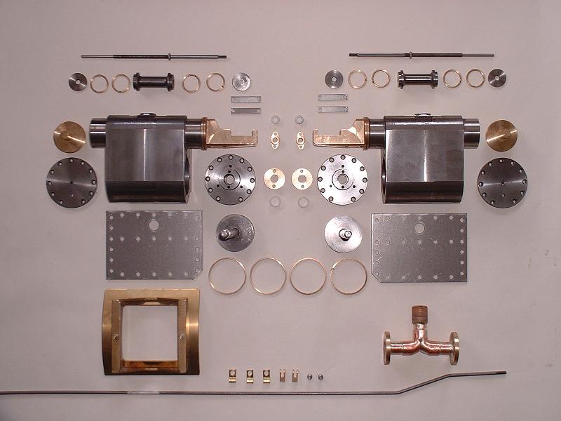
4/4/06 Kit 11 arrived at 8.00 this morning. It consists of the cylinders, pistons and valve pistons, the blastpipe and smokebox saddle, and the cylinder cock operating rod. The cylinders are beautifully machined from cast iron and the valve liners and guides are pre-fitted, presumably to ensure accurate alignment. The pistons are pre-fitted to the piston rods - they appear to be threaded on and then fixed with two punch marks. The rings for the pistons and valve pistons appear to be made from brass, and the gland packings for the rear cylinder and valve covers are PTFE cylinders.
5/4/06 I fitted the cylinder cock operating rod. This runs the length of the locomotive from the crank on the drag frame to the crank on the rod through the frames above the bogie, which were fitted in kits 6 and 9 respectively. It slides in three brackets attached under the horn stays on the left hand side of the frames.
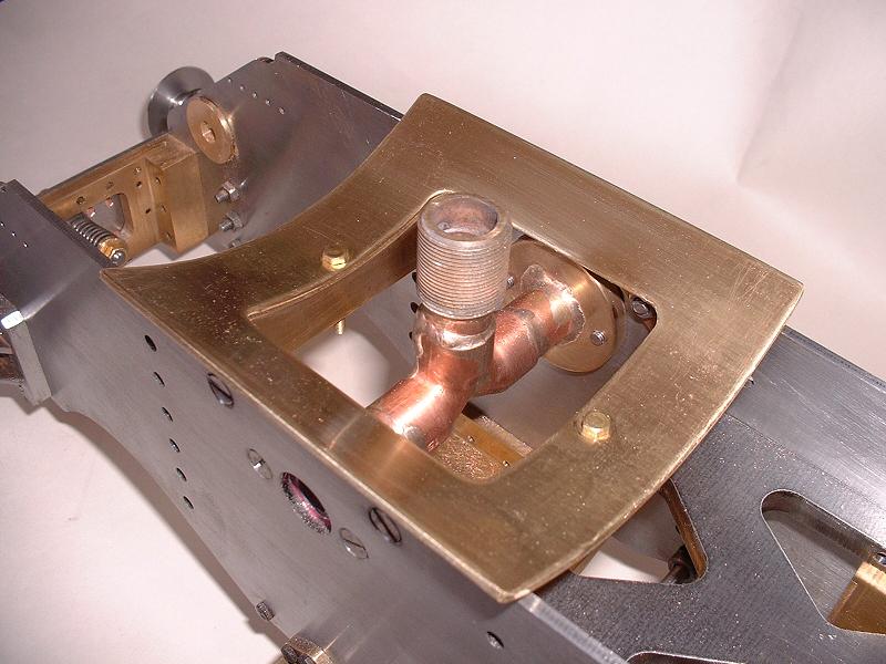
6/4/06 I started to fit the blastpipe, which is fabricated from copper pipes with brass flanges on the ends. It fits between the frames and takes the exhaust from the cylinders and directs it up into the smokebox. However, I soon found that the faces of the flanges were not parallel - there's a difference of 0.95mm between the widest and narrowest points - and so I couldn't get a good steam-tight fit to the frames. I've alerted Debbie and will need to send it back for replacement. I can't fit the smokebox saddle until the blastpipe is fitted, so I shall start on the cylinders.
7/4/06 I polished one of the cylinders to remove the machining marks - the flat faces were pretty clean but the curves at the top and bottom had lots of little ridges from the machining. This took several hours using a succession of grades of wet-and-dry sandpaper from 180 to 400 - I tried draw-filing, but this was counterproductive because it left scratches that took ages to polish out. Update 7/5/06: It turns out that kit 15 includes brass covers for the cylinders, so all this work was unnecessary! Pity they didn't say this in the instructions - I did wonder what the four screw holes were for.
 8/4/06
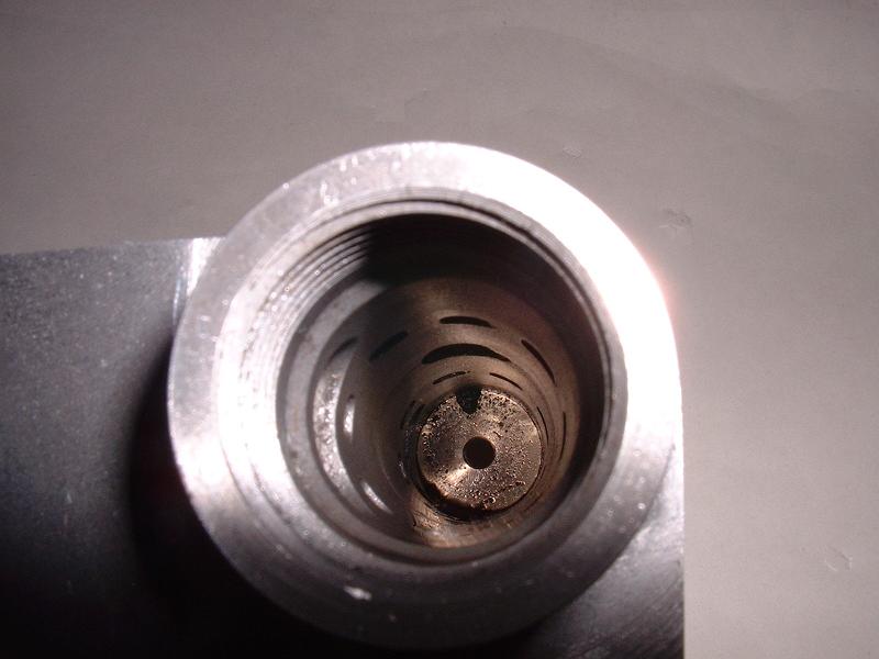
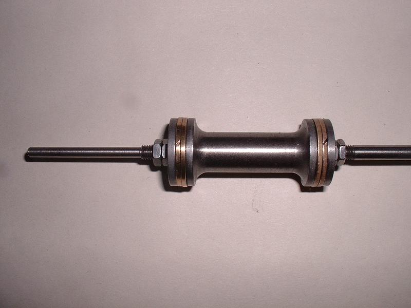
As a break from polishing the cylinders and while I wait for the skin to grow back on my fingertips, I tried installing one of the valve pistons. Each valve piston is made up of a central steel bobbin with a lip for two brass piston rings on each end, and a steel disk at each end to hold the rings on. The assembly is fitted to the threaded section of the valve rod, held by two M5 half-thickness nuts at each end. The hole through the centre is slightly larger than the thread diameter, allowing the piston to centre itself in the bore. The right-hand photograph shows the ports in the pre-assembled valve liner - an exhaust port on the left, then a ring of ports linking to one end of the cylinder, then the central steam inlet port at the top, then the other set of cylinder and exhaust ports. Each end of the valve piston slides across its cylinder ports, linking them alternately to the steam inlet and an exhaust port. I oiled the valve piston assembly and tried to insert it into the valve liner, but it was an extremely tight fit. There is a 45 degree lead-in taper at the front of the liner to help compress the rings, so getting them started in the bore was not a problem. I then tried it without the rings and it slid freely enough, although still quite a close fit. By turning the bobbin end for end and trying different rings I eventually got it moving reasonably smoothly with rings on one end, so I now need to keep trying different combinations and find out where the problem lies. I'm in contact with George who has the earlier Winson version of the Britannia, and he tells me that he and several other Winson builders replaced the brass valve piston rings with PTFE ones, because the brass ones leaked so much. I don't see much danger of leakage at the moment!
8/4/06
As a break from polishing the cylinders and while I wait for the skin to grow back on my fingertips, I tried installing one of the valve pistons. Each valve piston is made up of a central steel bobbin with a lip for two brass piston rings on each end, and a steel disk at each end to hold the rings on. The assembly is fitted to the threaded section of the valve rod, held by two M5 half-thickness nuts at each end. The hole through the centre is slightly larger than the thread diameter, allowing the piston to centre itself in the bore. The right-hand photograph shows the ports in the pre-assembled valve liner - an exhaust port on the left, then a ring of ports linking to one end of the cylinder, then the central steam inlet port at the top, then the other set of cylinder and exhaust ports. Each end of the valve piston slides across its cylinder ports, linking them alternately to the steam inlet and an exhaust port. I oiled the valve piston assembly and tried to insert it into the valve liner, but it was an extremely tight fit. There is a 45 degree lead-in taper at the front of the liner to help compress the rings, so getting them started in the bore was not a problem. I then tried it without the rings and it slid freely enough, although still quite a close fit. By turning the bobbin end for end and trying different rings I eventually got it moving reasonably smoothly with rings on one end, so I now need to keep trying different combinations and find out where the problem lies. I'm in contact with George who has the earlier Winson version of the Britannia, and he tells me that he and several other Winson builders replaced the brass valve piston rings with PTFE ones, because the brass ones leaked so much. I don't see much danger of leakage at the moment!
9/4/06 I did get the valve piston sliding smoothly late yesterday evening. It's fairly tight, but will no doubt bed in when I run it on air. I think the problem was that the piston rings are slightly oversize, and so when compressed in the bore the angled slit in each ring closes up completely and causes the ring to splay apart slightly at the slit. This causes it to lock up in the bobbin. By fitting the locknuts so that there is a tiny amount of end play on the bobbin, the rings have room to spread. I'll seek advice on whether to open out the slits slightly or leave it to run itself in.
 11/4/06
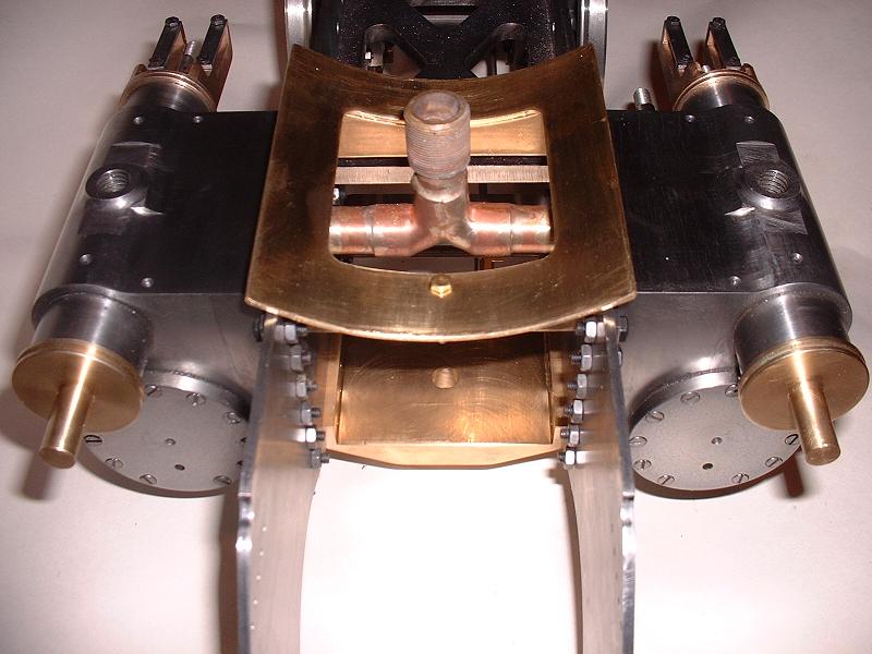
Just back from a couple of days sailing - chilly but invigorating. The consensus seems to be that I should not alter the valve piston rings, but leave them to run themselves in. The replacement blastpipe arrived this morning, and this fits nicely between the frames. Modelworks supply four gaskets in case extra thickness is needed, and I found that one on one side and two on the other gave the right fit. I then filed the sides of the smokebox saddle flange to fit between the frames - the instructions do say that this may be necessary, and I had to remove about 0.5mm to get a good fit. I found that 10 of the 38 M4x10 countersunk screws included in this kit have distorted threads and can't be screwed into an M4 nut - just as well I noticed this before trying to force them into expensive castings. I've asked Debbie for some replacements. Ted tells me that the two thin bolts used to hold the saddle to its frame are just temporary and the holes are threaded to take larger bolts securing the smokebox and saddle to the frame in kit 14.
11/4/06
Just back from a couple of days sailing - chilly but invigorating. The consensus seems to be that I should not alter the valve piston rings, but leave them to run themselves in. The replacement blastpipe arrived this morning, and this fits nicely between the frames. Modelworks supply four gaskets in case extra thickness is needed, and I found that one on one side and two on the other gave the right fit. I then filed the sides of the smokebox saddle flange to fit between the frames - the instructions do say that this may be necessary, and I had to remove about 0.5mm to get a good fit. I found that 10 of the 38 M4x10 countersunk screws included in this kit have distorted threads and can't be screwed into an M4 nut - just as well I noticed this before trying to force them into expensive castings. I've asked Debbie for some replacements. Ted tells me that the two thin bolts used to hold the saddle to its frame are just temporary and the holes are threaded to take larger bolts securing the smokebox and saddle to the frame in kit 14.
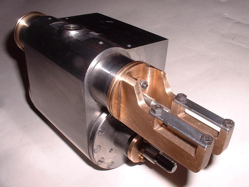
12/4/06 I finished polishing the first cylinder and its valve guides. After a bit more working to and fro by hand, the valve piston now slides fairly easily without needing any end play on the bobbin - I've set the locknuts just slack enough to allow the bobbin to slide sideways and align itself in the bore.
 13/4/06
The replacement M4 screws arrived this morning and the quality is noticeably better. I polished the cylinder bore with 1200 grade wet-and-dry, stretched the two brass piston rings over the piston and into their slots, and inserted the piston into the bore. It slides smoothly and seems to be a very good fit. I fitted the front and rear cylinder end plates, with gaskets smeared in steam oil (Ted kindly gave me a little pot of this when he visited). These are each fixed with 11 countersunk screws, but I'm told there are brass cover plates in the next kit to hide the screws. The very last screw hole in the rear plate turned out not to have a thread in it, so I had to undo the other 10 screws again and I gingerly tapped the hole in the cylinder block. The set of M3 taps that I bought to solve a similar problem in kit 2 came into their own - probably cheaper than posting a 7lb hunk of cast iron back to Modelworks, and certainly quicker. I then fitted the glands to the valve and piston rods. These consist of PTFE cylinders fitting around the rods and into recesses in the rear plates, covered by brass plates held by two studs and nuts. These are adjusted to compress the PTFE just enough to seal the joint without causing too much friction. The instructions still refer to graphited cord as the packing material, so the PTFE must be a recent change - it should make maintenance easier. The main piston seal was a close fit without any further compression - any tightening of the adjusting nuts caused it to lock up completely, but no doubt it will run in. The studs for the valve gland, which have Allen key sockets, really need an extra long Allen key to get between the valve guides. Ted told me I'd need one, and I now see why. Since I didn't have one, I temporarily locked two nuts onto the end of the stud and used a nut spinner to screw it in. Finally I filed and fitted the two steel top bars to the valve guides. This completes the first cylinder, apart from fitting the back plate and bolting it to the main frames. It's taken a lot of polishing and fitting, but I'm pleased with the end result.
13/4/06
The replacement M4 screws arrived this morning and the quality is noticeably better. I polished the cylinder bore with 1200 grade wet-and-dry, stretched the two brass piston rings over the piston and into their slots, and inserted the piston into the bore. It slides smoothly and seems to be a very good fit. I fitted the front and rear cylinder end plates, with gaskets smeared in steam oil (Ted kindly gave me a little pot of this when he visited). These are each fixed with 11 countersunk screws, but I'm told there are brass cover plates in the next kit to hide the screws. The very last screw hole in the rear plate turned out not to have a thread in it, so I had to undo the other 10 screws again and I gingerly tapped the hole in the cylinder block. The set of M3 taps that I bought to solve a similar problem in kit 2 came into their own - probably cheaper than posting a 7lb hunk of cast iron back to Modelworks, and certainly quicker. I then fitted the glands to the valve and piston rods. These consist of PTFE cylinders fitting around the rods and into recesses in the rear plates, covered by brass plates held by two studs and nuts. These are adjusted to compress the PTFE just enough to seal the joint without causing too much friction. The instructions still refer to graphited cord as the packing material, so the PTFE must be a recent change - it should make maintenance easier. The main piston seal was a close fit without any further compression - any tightening of the adjusting nuts caused it to lock up completely, but no doubt it will run in. The studs for the valve gland, which have Allen key sockets, really need an extra long Allen key to get between the valve guides. Ted told me I'd need one, and I now see why. Since I didn't have one, I temporarily locked two nuts onto the end of the stud and used a nut spinner to screw it in. Finally I filed and fitted the two steel top bars to the valve guides. This completes the first cylinder, apart from fitting the back plate and bolting it to the main frames. It's taken a lot of polishing and fitting, but I'm pleased with the end result.
14/4/06 I started polishing the second cylinder. When checking the kit contents last week I'd noticed that the second piston could be unscrewed by hand from its piston rod, despite ostensibly having been secured at the factory with two punch marks across the end of the thread. I contacted Debbie to suggest fixing it on with Loctite, and she said I could Loctite it and then 'peen' it again. I think 'peen' is a technical term for whacking with a hammer. On reflection I decided not to use Loctite, since I wouldn't then be able to tell if the peening had worked, and I'm not sure how well Loctite will stand up to superheated steam. So I just hammered in two deep indents with a centre punch, which took all of two minutes, and it now feels rock solid. I'm glad I spotted this, since a loose piston hitting the end of the cylinder could cause a lot of damage to the motion.
16/4/06 I've now finished polishing the second cylinder and started to fit the main and valve pistons.
17/4/06 I finished fitting the piston and valve piston and their glands to the second cylinder, achieving a smooth fit without too much effort this time. I found and fixed another untapped hole in the cylinder, this time for one of the front cover plate screws.
 19/4/06
Just back from another couple of days sailing in the Solent - we stayed overnight at Buckler's Hard on the Beaulieu river. As the weather warms up we will spend more time away on the boat and this may slow down progress on the locomotive a little. This evening I've cleaned up the cylinder backplates and bolted them to the cylinders, sealing the joint with the Foliac supplied. Foliac seems to be a mixture of oil and graphite, designed to withstand steam pressure. I then bolted the backplates temporarily to the main frames, omitting the gaskets for the time being until I'm ready to fix them permanently. One minor problem is that the cylinder drain cock levers are immediately underneath the bosses of the rear cylinder covers and their grub screws protrude and foul the bosses. I'll need to shorten the grub screws, or get some replacements. This completes kit 11 - I'll order kit 12 tomorrow.
19/4/06
Just back from another couple of days sailing in the Solent - we stayed overnight at Buckler's Hard on the Beaulieu river. As the weather warms up we will spend more time away on the boat and this may slow down progress on the locomotive a little. This evening I've cleaned up the cylinder backplates and bolted them to the cylinders, sealing the joint with the Foliac supplied. Foliac seems to be a mixture of oil and graphite, designed to withstand steam pressure. I then bolted the backplates temporarily to the main frames, omitting the gaskets for the time being until I'm ready to fix them permanently. One minor problem is that the cylinder drain cock levers are immediately underneath the bosses of the rear cylinder covers and their grub screws protrude and foul the bosses. I'll need to shorten the grub screws, or get some replacements. This completes kit 11 - I'll order kit 12 tomorrow.
20/4/06 Following a suggestion from Ted, I drilled and tapped new M3 holes for the grub screws in the cylinder cock levers at 90 degrees to the originals.
| Next Kit | Previous Kit | Index |